Tuesday, December 15, 2020

38 - Canopy & Window (finished); 42- Misc (attached foot steps); 47 - Cowl Baffle (closeout; oil door); 51 - FWF Misc. (various); Other (moved fuselage to hangar!)

First and foremost, I moved the fuselage to the hangar - specifically Parkers Towing and Transport moved the fuselage, and spent a good deal of time designing ramps for the main wheels for transport.  The Parkers are great people, and were very interested in all aspects of my RV-14A - most importantly, they took great care to secure and transport my bird.  I highly recommend them if you live in central Florida; they drove 50 miles each way for the transport, and now that they have transported two Van's aircraft (my buddy, Ken B's RV-14A and now mine), they are pros. 

The rest of the past 2 weeks involved a bunch of odds-and-ends, in an attempt to finish as much stuff in the workshop prior to moving the fuselage.  Specifically, I did the following: 

- finished attaching Koger sunshade; cleaned canopy and removed some of the inside protective plastic (for sunshade); painted baggage covers for steps

- tightened alternator pulley/belt and torqued and safety-wired bolt; attached boot to p-lead of magneto

- lower cowl closeout completed w/distal part of sniffle line attached to it; attached step attach covers in baggage area (used thin nylon #8 washers so paint doesn’t chip when screws tightened)

- greased nosegear Zerk fitting with blue marine grease (had to push out the Aeroshell 5, which is more hygroscopic); added 2000deg fireshield barrier to “red cube” fuel flow transducer, since so close to exhaust pipe; prepared oil cooler scat tubing

- painted baggage floor closeout and access panel from baggage area to tailcone; finished oil door; vacuumed tailcone, tied up loose wires in tailcone

- cleaned baggage area and tailcone with damp cloth; closed out baggage area and passthrough to tailcone; started installing aft window (siliconed screws in roll bar; loose attach of 22 of 29 screws in aft section of window)

- finished installing and prosealing the aft window

- cleaned garage, moved plane outside to attach canopy (with wife and daughter helping); realized aft edge of canopy was touching parts of the aft window, so sanded and scraped aft part of canopy to ensure adequate gap (4 iterations - pain in the ass, but it’s done)

- prepped plane and workshop for fuselage move (final prep)

- moved the fuselage to airport hangar using Parker’s Towing; cleaned hangar; cleaned workshop some more

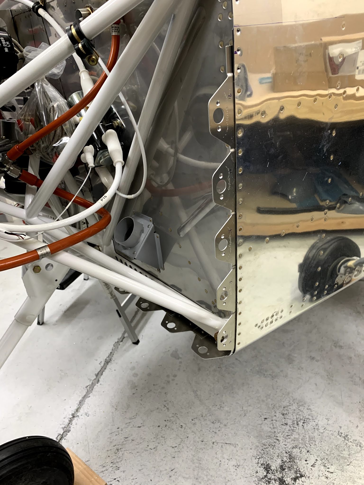
Here's a pic of the first step of the move:

Sunday, November 29, 2020

Avionics (canopy wiring); 38 - Canopy & Window (seals and Koger sunshade); 42 - Miscellanea (foot steps)

I didn't accomplish that much during the past 2 weeks, largely because I diverted some time to register the bird with the FAA, and start getting current again with a local flight school (and I completed a written exam, which took me about 6 hrs!).  Formal retraining starts this week.  Back to the bird:  I'm at the "90% done, 90% to go" stage, and formulated a long punchlist of stuff I want to accomplish before I move the fuselage to the hangar in a few weeks, as well as what is needed to finalize the plane prior to its airworthiness inspection. Here is a short list of tasks I completed these past weeks:

- attached head unit for ELT; completed SB-00027 (nosegear cutout and beefy washer); cut and attached LED glareshield light strip (1 extra segment, per Ken B.); started wiring canopy wires to the male molex pins on canopy molex connector

- finished canopy wiring, adhered wires with RTV silicone (note - the LED light strip’s tape does not adhere well - may need to RTV silicone that as well - or use Pliobond, which I ordered)

- attached static line to GSU25 and G5; attached 1/8” NPT straight fittings to pitot/AOA on GSU25 and pitot on G5

- attached some seals to canopy front, some of which used Pliobond to stick better; reattached LED light strip

- attached forward seal to canopy

- attached foot steps (powder coated black a few months ago)

- attached side canopy seals; attached Koger sunshade    

Started the cutout for part of the recent service bulletin (SB-00027):   

Thursday, November 12, 2020

Avionics (lots of shizzle)

I completed a lot of avionics-related tasks during the past ~two weeks, including powering on the panel for the first time!  Thanks to Sean M., I have a temporary ground power unit hooked to the aircraft, supplying about 14V (need to have between 13-15V to charge the LiFePO4 IBBS), and I can spend a couple hours at a time playing with the settings instead of only 10-15min with the ship's battery. Specifically, I did the following the past two weeks:

- finished tidying all wire bundles FWF; routed and terminated all grounds (34 in total) to “forest of tabs”

- wired voltage regulator for backup alternator; wired a few other loose wires; attached battery; attached two Comant COM antennae; attached (temporarily) transponder blade antenna

- routed RG400 and connected BNC male connectors to all 4 ends of the coax that goes to the Comant antennae

- fabricated and painted shelf for GPS antennae; routed RG400 for the main GPS antenna (from GTN750xi); ordered RG400 and female BNC to connect G3X "el cheapo" antenna

- tidied some of the avionics wires; routed main & G3X GPS antennae RG400 wires and mounted both antennae to shelf above baggage compartment; installed GTR20 (remote Com2) and voltage regulator for backup alternator to rails (fabricated previously); installed trickle charger harness to battery

- connected transponder and attached right avionics shelf; figured out LED strip light connections; troubleshot rocker switch backlighting issue (3 switches weren’t lit; bad wire crimp for two); wired G3X GPS antenna; wired GTN750xi Nav to Archer antenna (temp. install)

- attached power supply to airplane to test avionics without draining battery, and to charge the IBBS and G5 (since they supposedly need >=13.8V to charge - correction: 13-15V) ; Comms worked well in receive mode - used headset and separate handheld transceiver on 123.45MHz; programmed avionics (started)

- installed most components of the ELT (except head unit, since waiting for battery)

- attached labels to push/pull control knobs; attached canopy avionics wires to molex connector; routed and attached 2 wires to canopy open/closed switch; cut and attached glareshield edge trim; started planning SB for nosegear washer and cutout; cut LED light strip to size (plus one segment, according to Ken B.) 

The next set of pics are the final tidying of FWF wires, hoses, cables, etc:


Tuesday, October 27, 2020

47 - Cowl Baffle (finished); 50 - Control Cables (prop cable); 51 - FWF Misc. (route mag harnesses); Avionics (FWF wire terminations)

A lot of miscellaneous tasks were accomplished during the past couple of weeks, the most noticeable of which was wiring the various FWF sensors to the avionics, as well as finishing the damned cowl baffle. They both are looking good though.  Oh, and I had a visit from my buddy, Ken B., who gave me an initial Pope's blessing for the FWF - before we do the first engine run-ups, he'll go over everything with a fine-toothed comb.  For now, most everything was good, and a couple things were fixed.  Specifics for the past week are listed below:

- attached magneto/emag cooling tubes; sealed baffles with lots of red RTV

- formed and attached clamping strips to bottom cowl air inlets; epoxy-floxed between cowl and strips

- sanded bottom cowl outboard and inboard air inlets to curve to match the baffle’s width; added epoxy/flox to top cowl to eventually sand down to match bottom cowl (outboard edges of air inlets)

- sanded top and bottom cowl outboard inlets to match each other; attached inlet seals (except one screw - need a longer screw); attached foam block to top cowl with red RTV; mostly done with the cowl baffle section!

- installed prop bracket & cable; partially attached sniffle valve and tubes/hoses; ; finished installing alt. air cable

- Route, adel-clamp, and attach spark plug harnesses (from Slick magneto and P-mag)

- Ken B. visited to check out my FWF and avionics install to date - great to catch up, and I appreciated the advice!

- installed CHT and EGT probes; messed with routing wiring for EGT and CHT (K-type wires); inventoried misc. hardware and supplies that I bought from Ken. B.

- worked on wiring under panel; routed and wired CHT and EGT probes

- wired a couple FWF sensors (fuel pressure, oil pressure)

- wired master solenoid, starter solenoid, oil pressure switch, oil temp, main amp shunt (primary alternator), aux amp shunt (backup alternator), started tidying all wire bundles FWF

Using binder clips to pre-bend the stuff rubber seals:

Sunday, October 11, 2020

47 - Cowl Baffle (baffle rods; snorkel & air filter; ramp cones; baffle seals)

Another two weeks have passed, and I still haven't finished the cowl baffle section! Lots of little steps, many of which require fitting and refitting (e.g. snorkel).  I received the interior this week (yeah!), and look forward to installing it in the plane in a few weeks, once I finalize the avionics wiring and a few other tidbits.  Details of what was accomplished are as follows: 

- messed with the snorkel for far too long - doesn’t fit perfectly, so I will have to build up the flange using flox (edit: I just sanded a bit, since there was plenty of material); tried cutting baffle tension rods and using a die to thread the ends, but I had a crappy die and work-hardened the ends by using a dremel tool.  Contacted Ken B., who suggested a die grinder and better 6-32 die

- threaded rod ends using a better, high-speed steel 6-32 die (McMaster-Carr), and attached and tensioned the rods to the baffles

- fit, trimmed, sanded, drilled, floxed and epoxied snorkel

- cut alt air hole, drilled and floxed alt air inlet; unpacked and inventoried interior for plane!

- formed and attached ramp cones; final-installed snorkel and air filter (safety-wired snorkel to fuel servo); everything fits fairly well!

- attached baffle seals; routed top ignition wires (had to enlarge holes for the 5/16” p-mag wires); brushed on additional layer of epoxy on top cowl where baffle seals will touch

Here are two of the baffle tension rods, attached and torqued - those were a pain to install. Note that I used two metal locknuts (one as a "jam nut"), since the -06 sized nuts are really not very tight:


Saturday, September 26, 2020

47 - Cowl Baffle (attached 4 main baffles); Other (ANL fuses; shunts)

Not as much progress during the last two weeks as I had hoped, but much of this time was spent thinking and reading about the next steps with the firewall-forward wiring - mostly how and where to attach and wire the ANL fuses and shunts. There are many different ways of tackling this with 2 alternators and 1 main battery. Some folks use 1 shunt after fuses and tie in both alternators, and sometimes the battery, to measure current for all 3.  While this would work, in conjunction with a voltmeter (built into the G3X), I had SteinAir specifically wire two sets of shunt wires so I could monitor both alternators separately. Also, I had a little issue with the oil filler tube - it came cross-threaded, and thus couldn't be installed straight. No worries - a couple emails to Lycoming and I received a new oil filler tube with no problems (and this one installed relatively easily).  Specifically, these items were accomplished:

- attached ANL fuse holders and shunts to firewall (w/wife helping); attached all 8AWG cables/ring terminals from alternator to ANL fuses to shunts to unswitched side of starter contactor.  Shunts will measure current flowing from primary and secondary alternators

- deburred, drilled, and riveted cylinder baffles and left aft baffle

- deburred, drilled and riveted right aft baffle and cylinder #3 bridge; attached aft and forward center brackets to engine; applied RTV sealant to left and right aft baffles

- installed both aft baffles to engine (mostly - some nuts/screws need to be final-tightened later)

- assembled left and right forward baffles and air ramps, qqand added strips of red RTV where they touch the engine (will need to cure for 1-2 days before installing on engine)

- installed oil filler tube (w/safety wire); installed front left and right baffles and tightened all screws/nuts

A little out of order, but here is the final wiring for the ANL fuses and shunts (pic below).  One fuse per alternator, and one shunt per alternator, so I can read the current for either on the G3X EFIS.  No need to read battery current - if I'm at the stage whereby I need to know how much current I'm drawing from the battery, then both my primary and secondary alternators have failed (unlikely), and I will be landing ASAP.  Moreover, the EFIS screens have an IBBS (integrated backup battery system), and the G5 backup system has it's own 1 hr internal battery, so the chances of running out of juice are essentially nil. If all else fails, the engine will still run without any external power, and I can communicate via a handheld radio that I carry.  I am a belt, suspenders, another belt, and a few more suspenders kind of guy:   

Friday, September 11, 2020

48 - Exhaust (finished install); 49 - Fuel & Oil System (installed most hoses/lines); 50 - Control Cables (installed throttle and mixture)

 Lots of little odds-and-ends were accomplished during the past two weeks - I can certainly understand the phrase "90% done, 90% to go!"  On one hand, I feel like this plane should be flying in a month - on the other hand, every time I think that, I find 10 more tasks I need to accomplish.  Oh well - I can't believe I'm still having as much fun today as I did in July 2018 when I started this project!  I also wish the building part will never end (BUT, I want to fly again soon, so not really).  Time to start scheduling my eye exam, get my Basic Med signoff, get current with a CFI, and put my name on a waiting list for transition training.  Here are the details for the past 2 weeks: 

- installed one more scat hose

- installed penultimate scat hose for heating air vents; played around with wiring and hoses for rest of avionics and engine install (complex!)

- installed Airwolf remote oil filter; installed a few more FWF oil/fuel lines and other misc. stuff

- installed oil pressure sensors and oil pressure switch (had to disassemble manifold bar on firewall to do so); installed a couple oil lines; deburred and primed parts of oil cooler; installed breather tube

- oil cooler mount and other related items were installed or prepped

- Finished installing oil cooler; installed p-mag manifold pressure tube, routed and temporarily attached Aircraft Specialty manifold pressure lines (not tight yet); wired p-mag control plug/harness and installed to p-mag (difficult as shit to reach in there)

- installed hoses to oil cooler; dabbed more red RTV to seal holes in oil cooler shroud; routed some avionics wires (temp.); accidentally knocked identifying shrink tubing off of CHT1 and CHT3, and had to disconnect several avionics bundles and unscrew left shelf, strip wires, do a conductivity test, and then relabel wires and reassemble everything (PITA!); final-torqued and installed manifold pressure lines; installed wires to manifold pressure sensor

- enlarged holes and installed control cable bracket; routed and partially installed throttle, mixture, prop, and alt air cables; rerouted some avionics wires (esp. the big wire bundles/connectors, which needed to go aft of the horizontal rudder pedal bar)

- installed cabin heat cables to right and left heat vents; continued installing throttle cable and cable guide; 

- installed the throttle bracket/cable and mixture bracket/cable

- rerouted some of the avionics wires to go through the center firewall passthrough; drilled holes for ANL fuses and shunts on firewall; installed “forest of tabs”

Scat hose connected between the two heat muffs:

Wednesday, August 26, 2020

Other (avionics install., cont.); 43 - Engine Install (sensors); 45 - Cowling (inlet ramps); 48 - Exhaust (exhaust pipes and scat tubes)

During the last ~2 weeks I bounced around a bit, depending on what needed to be accomplished (and to afford time for curing/drying/cogitating/omphaloskepsis).  Nothing earth-shattering, except to mention that ALL the remote boxes have either been installed or holes have been drilled for their eventual installation. Having so many remote boxes made it quite a challenge to locate everything behind the panel - but they will all fit.  Specifically, I accomplished the following:  

- drilled a few holes to attach Garmin boxes; lots of planning; modified left avionics shelf for GAD29 and IBBS attachment

- installed GEA24, GAD27, GAD29, IBBS and left avionics panel

- installed CO detector, identified and routed many loose wires through firewall passthroughs; took off upper and lower cowl, and locked remaining camlocs 

- uninstalled GAD29, IBBS, and 4 connections to GEA24; drilled 4 holes for main power bus connector and attached connector; reattached aforementioned items

- sanded inlet ramps, epoxy/flox/micro of aft edges (will smooth out so baffle rubber will close neatly around the prior gap)

- sanded epoxy/micro on upper cowl; bondo-filled all holes holes and sanded (3x repeated); coated all sanded areas with light layer of epoxy

- installed fuel pressure sensor and manifold pressure sensor; completed a few odds-and-ends

- started installing the exhaust pipes - installed the hanger for tailpipe, and placed and loosely attached the aft and forward exhaust pipes (used nickel anti-seize paste at slip joints)

- finished installing exhaust system; torqued flange nuts 16 lb-ft; drilled out 2 LP4-3 rivets from right heat vent and installed cover w/red RTV

- prepared and installed heat muff assemblies; prepared scat hoses for vents (cut, trimmed, RTV’d the length of each hose); organized hardware

- Installed vent t-splitter that directs hot air to left/right cabin floor vents; installed a few scat hoses, while leaving others off for access (for fuel line penetrating cabin - prosealed the fitting to the firewall, but will need to final-torque nut and fuel line later)

View behind the panel - damn, that's a lot of wires!  Avionics shelf was fabricated (next pics) to hold the IBBS battery (black rectangular box in the center) and GAD29 (underneath shelf; not shown):

Thursday, August 13, 2020

45 - Cowling (finished camloc installation); Other (avionics panel install)

Recently, I passed a milestone: 1500 hours working on this project over the last 2 years and 1 month ... and it still excites me every time I go into the workshop!  This was a big couple of weeks - first, I finished the camloc installation, which was a pain in the ass, but they look great and hold the cowling very well.  Second, and perhaps most important, I started installing the avionics panel!  Lots and lots of wires and gizmos behind the panel, but the panel itself is a beaut and I am glad I went with the larger GTN750xi instead of the smaller GTN or the even smaller GNX/GNC boxes.  Real estate matters, esp. flying IFR.  Specifics are as follows:

- installed camloc flanges on the sides and lower part of fuselage

- epoxied the inside of both cowlings (did this early in the camloc install process, so I don’t have to uninstall all of the camloc grommets later)

- added two more camloc flanges to upper cowl (the ones that are aligned with the side flanges of the lower cowl)

- added two camlocs to upper cowl; positioned and trimmed aft edge of lower cowl (needed 1/8” or so trimming for most of it); had to grind off some of the corners to make the cowl fit well (and bend the camloc flanges back a bit in the lower corners); wife helped hold aft section of lower cowl

- installed side camlocs on lower cowl; drilled holes for bottom camlocs on lower cowl; trimmed lower aft edge of lower cowl; installed two wires (one to alternator and one to starter) 

- installed camloc retainers on bottom of aft lower flanges (4 per side); cut upper flange of lower cowl and sanded to trim line (near-final; only needs a few touch-ups)

- spacing and drilling flanges for the horizontal sections of the lower cowl; countersunk all holes in lower cowl for flange rivets; countersunk flanges to accept retainers

- riveted flanges to lower cowl; drilled holes and installed grommets in upper cowl; fabricated screw mechanism for grommets that are close to engine mount bolts; installed retainers in lower cowl; essentially completed rest of Camloc install (except for locking the remaining retainers); drilled #19 holes in forward part of cowls

- Delivery, uncrating and partial unpacking of SteinAir panel!

- finished unpacking panel

- trimmed, clecoed and floxed inlet ramps onto upper cowl; installed upper cowl on fuselage; prepped oil door and drilled holes (1/4”) to install camlocs

- installed panel onto panel frame on fuselage (with wife and daughter); enlarged hole for canopy release; drilled and deburred 6 holes for Nav’s mounting bracket; placed all wires in respective areas; installed circuit breaker panel (needed to modify support by bending forward flanges aft 90deg); drained water in air compressor

- Installed Nav and audio panel; planned placement of other boxes behind panel

- installed transponder on shelf on right side (shelf had to be altered to fit, and 4 brackets were constructed from 0.025” aluminum, bent into angles); started remote comm install; checked placement of vent cables and how they impinge on avionics shelves; retied right cable bundle

Installed left side flanges (Camlocs):

Monday, July 27, 2020

43 - Engine Installation (misc. install.); 44 - Spinner & Propeller (installed prop.); 45 - Cowling (installing Skybolt camlocs)

This is my 100th blog entry, and it has a lot of small tasks related to the Finish and FWF kits.  Specifically:

- installed fuel servo; loosely installed a lot of adel clamps to engine and mount; attached starter cables to starter; worked with Steve from Aircraft Specialty to install VA-102 hose (needed to clock the fitting on the fuel pump differently than Van’s instructions); installed fuel flow red cube and hoses/connections that lead from fuel pump to fuel servo to fuel spider; installed VA-139 only to fuel pump (needs to be loose now, so I can install exhaust system later)
- installed throttle cable bracket; installed alternator and belt; installed a few more adel clamps
installed spinner plate assembly to propeller; installed propeller to engine (final-torqued and safety-wired); installed forward spinner bulkhead
- filed spinner openings to fit prop blades; sanded areas that contact the spinner bulkheads, and then brushed on thin layer of epoxy
- Prepped cowling; attached upper cowl to fuselage to measure distances for Camloks; started figuring out how Camlocs are installed
- trimmed camlocs, remeasured camloc distances, and match-drilled one half of them to fuselage
- match-drilled remaining camlocs, and removed, deburred, countersunk, and riveted them to upper fuselage; bent camlocs so upper cowl sits flush; started fitting of upper cowl to fuselage, including measuring and trimming of aft edge (lots of remove & reinstall steps)
- finished filing aft edge of top cowl (tight fit of 0.001-0.032”, per painter, so his crew can finish down to spec); match-drilled #30 holes into camloc drill guides using Mark A.’s “3 line” technique; upsized holes to 15/32”, sanded w/ dremel to just fit the grommets; attached temp o-ring retainers to grommets; riveted receptacles to flanges and temp. screwed all camlocs with the pins still engaged (i.e. “unlocked”) - all top cowl camlocs seem to work well!
- installed camloc flanges on the sides and lower part of fuselage

Installed fuel servo, and Aircraft Specialty Fuel lines with integrated fire sleeves:

Tuesday, July 14, 2020

40A - Gear & Engine Mount (nose gear & wheel); 46A - Leg & Wheel Fairings (intersection and nose gear fairings); 43 - Engine Installation (mounted engine to fuselage!)

The engine has been mounted to the fuselage!  All other crap I did the past two weeks was incidental to this major milestone - and thanks to Ken B., the install went quite smoothly.  Prior to that, I had received the nose gear leg and installed the nose gear and wheel, and did a bunch of composite work.  I'm really not a fan of fiberglass - almost a month of working on the 13 fairings for the wheels/legs and I'm still not quite finished. But, with the engine on, I'll be moving on to engine-related tasks for a while.  Here is what was accomplished during the past two weeks:

- installed nose gear leg and link assembly
- installed axle flange and nose fork, torqued the -24 nut until ~30lb of force felt per pulling with a fish scale (a little more than 26lb required, since will loosen over time); installed nose wheel
- removed intersection fairings and sanded/trimmed; floxed a lug to encase nut that attaches the training edge of each upper intersection fairing
- removed tape and excess flox from nut lugs; #27 drilled and #40 countersunk upper intersection fairings (attached to fuselage); removed main wheel fairings, and reattached halves with screws; drilled and deburred holes for nutplates in fairings; countersunk holes for nutplates
- figured out how to get fuselage into level flying position whilst having the nosewheel barely touching the ground; drew longitudinal center line on garage floor; marked standoff locations; aligned nose wheel fairing
- Cut slot in nose wheel fairing; aligned fairing in pitch; drilled bracket holes (magnet technique) and standoff pilot hole; tapped bracket holes; drilled standoff holes to just under 1” wide (will finish later, after - I received the proper screws to hold standoffs - was using shorter screws with washers for the initial fits); floxed brackets to nose wheel fairing rear
- Final drilled nose wheel fairing to brackets; installed nutplates to brackets; primed brackets; attached brackets to wheel fairing and attached to nose wheel; final fit of fairing (needed trimming to clear nose gear leg through the wheel’s range of motion)
- trimmed and aligned nose gear leg fairing; drilled nose gear leg fairing and hinge
- deburred, countersunk and riveted hinge halves to nose gear leg fairing; started initial fit of fairing (trimming, fitting, trimming again…)
- drilled #19 holes in fairing to attach to nose gear leg; attached nutplates to nose gear leg; final-trimmed fairing
- installed last oil fitting; cleaned and prepped workshop to install engine; installed engine onto dynafocal mount (w/ Ken B.!)

Floxed intersection fairings, installed on fuselage and wheel pants, and then removed them to trim:

Wednesday, July 1, 2020

46A - Leg & Wheel Fairings (main and nose wheel fairings, intersection fairings, leg fairings)

Since I was still waiting for the nose gear, I begrudgingly trudged through 12 of the 13 fiberglass pieces that comprise the leg and wheel fairings.  Lots of progress on most of these parts ... and a very dusty workshop from sanding and sanding and sanding fiberglass.  Be resigned to have dust everywhere for a while. Specifically, I completed the following during the past ~12 days:

- finished fitting right gear fairings to each other; #40 match-drilled; cutout gear leg clearance hole; ensured all could be installed on right wheel/gear; floxed all 4 brackets to gear fairings and loosely attached with screws (did this process off the plane, since there was no way to verify proper seating of bracket if on plane)
- cleaned up floxed brackets; drilled, countersunk and riveted nutplated to aft fairings; drilled #27 and countersunk holes in forward fairings; both main wheel fairings are ready to mount onto plane
trimmed nose fairing halves; marked and drilled holes #40 into nose fairings; fabricated “v block”
- leveled nose wheel fairing and marked;  fabricated spacer and deburred bracket and located nutplates on bracket; lots of contemplation about this fairing
- checked main gear fairings for twist; secured trailing edges; modified hinge halves; drilled, clecoed and deburred hinges into one of the main gear fairings
- countersunk and riveted hinges to first main gear fairing; bent hinge pin and drilled hole for safety wire; completed all tasks for the 2nd main gear fairing
- worked on all 4 intersection fairings for the main gear (lots of sanding)
- attached main gear fairings with screws (they fit!); attached leg fairings and intersection fairings (on/off to prepare for drilling); drilled right intersection fairings
- drilled left intersection fairings; sanded all 4 intersection fairings (80grit); floxed two upper intersection fairings and installed loosely with #6 screws; received and opened crate with nose gear leg
- floxed and clecoed lower intersection fairings to main wheel fairings

The four main gear fairing halves, at some intermediate stage of completion:

Saturday, June 20, 2020

45 - Cowling (trimmed); 43 - Engine Installation (random stuff); 38 - Canopy & Window (latch system); 40A - Gear & Engine Mount (installed legs, wheels, brakes); 46A - Leg & Wheel Fairings (main gear nearly complete)

Another couple weeks of searching for items to complete, while I wait for Van's to deliver backordered items (COVID-delays, so understandable). Fortunately, they sent me the main gear legs and the latch torque tube, so I could get another week of work done toward installing the engine.  BUT, I still need the nose gear and link before installing the engine ... oh well, this forces me to continue picking at the fiberglass bits. Here are the details:

- clamped cowl halves together and started fine-trimming the spinner hole and ducts; lots of small areas to sand to get all four areas to fit nicely
- finished fine-trimming of spinner hole and air ducts; drilled #40 holes to cleco (for now) the area around the spinner; cleaned up for next project (dust everywhere!)
- removed fuel hose that goes from fuel servo to fuel spider to take measurements and pictures for Aircraft Specialty - they will fabricate an integral firesleeved hose for me, and hopefully include in their catalog for other RV-14A builders!  
- received backordered powdercoated torque tube from Van’s; installed canopy latch system; tested latch action inside and out - works just fine!  
- installed main gear legs; attached main gear leg axles (wife helped); checked alignment of axles (toe); installed main wheel and tire assemblies
- installed brakes and brake lines from fuselage to calipers (Aircraft Specialty!)
- trimmed and deburred oil door and oil door hinge
- prepped main gear fairings; fit and trimmed main gear fairings so the halves mate as precisely as possible
- drilled #30 main gear fairings for brackets and found that one aft fairing was mis-dimpled at factory; repaired drill holes in aft fairing using epoxy-flox; drilled left fairing and cut gear leg clearance hole; attached nutplates to fairing brackets; installed one bracket temp. on left gear/wheel
- attached other 3 brackets (temp) to gear/wheels; modified left wheel fairing halves to have 5/8” clearance for tire
- finished fitting right gear fairings to each other; #40 match-drilled; cutout gear leg clearance hole; ensured all could be installed on right wheel/gear; floxed all 4 brackets to gear fairings and loosely attached with screws (did this process off the plane, since there was no way to verify proper seating of bracket if on plane)

Finished trimming and fitting the forward parts of the top and bottom cowls - the two halves fit well together, so I drilled the requisite #40 hole: 

Sunday, June 7, 2020

43 - Engine Installation (misc.); 44 - Spinner & Prop (spinner plate and spinner cutouts); 45 - Cowling (trimmed to scribe lines)

In an effort to keep busy while I await a number of backordered parts from the Finish and FWF kits, I bounced around between tasks for the engine installation, spinner and propeller, and cowling.  Fortunately, a fairly heavy (~60 lb) shipment from Van's is en route and should be here on Wed - and I hope these are the powder-coated parts that I need to finish the canopy latch mechanism as well as the gear legs so I can put her on her feet.  The latter is needed before I attach the engine, which would be the next major step in (hopefully) a couple weeks.  Meanwhile, here is what I accomplished since the last post:

- attached a bunch of steel fittings to the engine; torqued nuts and attached more wires to the starter solenoid
- primed and attached manifold pressure sensor bracket; separated, deburred and riveted prop governor bracket assembly
- powder-coated steps (H&R Powder Coating in Orlando)
- figuring out how to install B&C backup alternator (i.e., hard-to-reach nuts), as well as the electrical connections to the e-mag - VERY tight quarters for both
- installed B&C backup alternator (torqued 3 nuts at 108 in-lb); what a pain in the ass 4th nut - need another tool to properly torque that nut; EDIT - got proper vacuum pump crow’s foot and wobble extension and it was easy to torque that 4th nut
- drilled #30, and cut spinner plate assembly with pneumatic nibbler and pneumatic belt sander
- riveted spinner back plate and doubler, and deburred edges; removed cutout sections of spinner;
marked scribe lines; started trimming cowl at the spinner and air-intake areas
- trimmed to scribe lines for all areas except the aft lateral lines on the bottom cowl; test-fit to determine interference in the front section (will need to trim a little more)

Finished installing the remaining wires to the master relay and starter solenoid.  After reviewing Ken B.'s and Turner B.'s installations of their alternator fuses and G3X shunt, a couple of these nuts will need to come off to accommodate the starter switch wire and main power switch wire. I'll deal with that once I receive the panel.


Monday, May 25, 2020

38 - Canopy & Window (complete); 39 - Seatbacks (nearly complete); 40A - Gear & Engine Mount (misc. tasks); 41 - Wing Attach (misc. tasks); 42 - Miscellanea (ready for paint); 43 - Engine Install (misc.)

Big news - the engine arrived this week! What a beaut - now, I just have to figure out how to prep it prior to mounting it to the fuselage.  Prior to that, I need to attach the gear ... but there's been a COVID-induced issue.  I've been waiting on a number of parts from Van's - essentially all the larger powdercoated parts in the finish kit (incl. gear legs), as well as the exhaust system for the engine.  After contacting them, COVID has hit their suppliers of these parts, so there is no projected ship date.   To keep forward momentum, I am going through each section and doing any task that I can logically do out of the standard order, and thus why this post has tasks from 6 different sections.  Here is a summary:

- installed defog fans; installed rear seal and torqued zone 3 of canopy; fiddled with canopy latch mechanism - pins still too tight (need to work it in)
- fabricated seat backs - still need to paint, so didn’t final-install the pins
- bolted engine mount to firewall assembly (with help from wife)
- separated and primed gear attachment angles; primed and installed upper gear braces (not final torqued yet, since waiting on 3/8” torque wrench); trimmed washer for nose gear leg; primed gear attachment bars
- final-drilled #17 holes in wing root fairings
- elevator pushrod assembly and priming; wing root fairings deburred and lower fairings bent around 1.25” PVC pipe
- engine delivery and uncrating
- determined best way to lift engine
- dimpled holes and installed nutplates to seat ramps; deburred  edges of almost all parts in the Miscellanea section; riveted motor cover assembly; riveted aft cover and doubler; attached shoulder harness cables; primed stick boot doubler and battery box attach angle
- temporarily installed battery; installed master relay and starter solenoid; installed sender mount to firewall (without oil and fuel pressure sensors, since I’ll need those from SteinAir)
- figured out how to install a Michelin Airstop tube and tire on the Matco nosewheel (final tire pressure = 35 psi)
- installed tubes and tires on main wheels (final tire pressure = 40 psi); packed grease into all 6 bearings (2 per wheel); installed bearings in main wheel and tire assemblies; torqued upper gear brace; installed elastomer pad; installed nose wheel and tire assembly, using Matco axle, spacers, and bearings

Assembled engine hoist:


Thursday, May 14, 2020

38 - Canopy and Window (fabricating the Fiberglass Fairing, Part 2 - COMPLETED)

Part 2 of fabricating the fiberglass fairing is shown below, following this summary:

- cut 2 layers of BID fiberglass on the bias, ready for pre-preg; retaped the perimeter of the fairing, readying for sanding tomorrow (after filler fully cures)
- sanded the epoxy/microballoon paste, applied second layer of tinted BID fiberglass cut on bias, pre-preg
- sanded fiberglass (80 grit); wiped with IPA; replaced black tape; applied skim layer of Aeropoxy Light (s.g. of 0.49!)
- sanded Aeropoxy Light (80 grit), re-applied Aeropoxy light in several slightly low areas, to try to get the transition close to perfect side-to-side
- sanded Aeropoxy light, sprayed with filler primer (SEM), and did 4 rounds of filling with “Icing” (like Bondo), prior to a final coat of primer.  Looks beautiful - the canopy fairing was well worth the ~25 hours I spent on it

Re-taped the perimeter with black electrical tape:


Sunday, May 10, 2020

38 - Canopy and Window (final installation of canopy plexiglass; fabricating the Fiberglass Fairing, Part 1)

After match-drilling the canopy and canopy frame holes, countersinking or dimpling as appropriate, the canopy went back on the canopy frame for riveting and final torquing of zones 1 and 2 (zone 3 will be torqued later). I also figured out an easy way to thread safety wire in the left rail of the canopy frame (for the canopy switch) - details below, and involve using sewing thread!

The next task is a dreaded step for many builders:  the canopy's fiberglass fairing, which provides a transition from the aluminum canopy frame to the plexiglass canopy.  Fortunately, I attended an EAA Sportair workshop titled "Fiberglass Techniques for RV Aircraft" led by Scott Vanderveen, who had us do a complete process for a mockup canopy fairing over the 2 day class (along with 2 other RV-relevant projects).  Scott's method differs from Van's quite a bit; I've provided many of the steps below, but unless you already know how to work with fiberglass, I highly recommend taking Scott's workshop. The major differences are:  1) the Van's-supplied templates to outline the fairing or cut the fiberglass pieces are not needed; 2) instead of cutting umpteen fiberglass pieces, some on the bias but most not, simply cut enough fiberglass all on the bias (important!) for 4 strips of BID fiberglass, 2.5" wide; 3) a strong structural adhesive is used to bond the fiberglass to aluminum (epoxy doesn't adhere well to bare aluminum), 4) all filler and fiberglass layers are tinted, so the result is a deeper black than the Van's method that has only the first layer or so of fiberglass tinted; and, 5) the finishing layer is Aeropoxy light - a wonderful epoxy paste that is strong yet can be easily sanded and shaped (unlike epoxy/flox/micro). So far, I've completed half the process - i.e., up to the point right before the second application of dual-layer BID fiberglass.  I've delineated each step with pictures, following these details from the past week:

- match-drilled #27 (w/reamer) all holes common to canopy and canopy frame; deburred holes; dimpled #27 holes in side skins; started prepping for interior paint
- painted interior of canopy frame assembly; deburred and machine-countersunk holes in canopy; separated seal retainers; cut notches in rear seal
- painted top of glare shield matte black; painted seal retainers gray; primed contact surface of canopy handles; installed safety wire (to eventually pull canopy latch switch wires, when avionics are installed)
- placed canopy back on canopy frame assembly; clecoed left side skin, loosely attached hardware on left side, and tried to “fish” 0.041” safety wire though the channel
- loosely attached screws/hardware on right side of canopy; riveted side skins to canopy; fished 0.041” safety wire through wire channel using thread and needlenose pliers; attached screws/hardware and seal retainers on aft part of canopy (tightened inboard 14 screws); fabricated and installed canopy wear strips
- separated and fit hinge covers; tightened screws in “zone 2” of canopy with my wife’s help; fabricated canopy clips
- riveted canopy clips to canopy frame assembly; sanded canopy (80 grit) and aluminum (220 grit); followed Scott Vanderveen’s canopy fiberglass transition, Day 1 (structural adhesive; flox/micro/tint epoxy fillet; 2 layer tinted BID fiberglass cut on bias, pre-preg)
- Day 2: sanded fiberglass (80 grit); brushed on thin layer of epoxy; used tinted dry micro/epoxy paste and a bondo spreader to form center fillet and fill some of the low spots

Final #27 drilling of the canopy and canopy frame:


Saturday, May 2, 2020

38 - Canopy and Window (finished canopy assembly; drilled canopy to canopy assembly)

This section is taking forever; but, a shout-out to Van's for such excellent engineering - the canopy frame is light as can be, and very strong. Once the canopy was match- and final-drilled, and clecoed to the canopy frame, it became even sturdier.  Note to other builders:  take your time drilling and use proper plexi bits (I purchased from Abbeon) until you hit metal, and then switch over to jobbers for the aluminum.  Here are the main details for the past couple of weeks (thanks to my wife for helping me mount and remove the canopy and canopy frame multiple times this session):

- clecoed and final-drilled canopy assembly; removed all clecos; riveted canopy handle assembly together and to the aft canopy frame (after deburring edges of all parts)
- countersunk canopy rail assemblies, canopy handles, and forward canopy rails; dimpled canopy side skin and main canopy skin; dimpled support flange; deburred all holes that were drilled; clecoed main canopy skin and forward canopy rails to the canopy frame assembly
- riveted canopy assembly and canopy frame closeout making sure to check each side is level every FOUR rivets
- riveted canopy rail assemblies to canopy assembly
- riveted canopy frame assembly to canopy assembly; attached switched brackets and canopy pin blocks to canopy assembly; installed canopy assembly on fuselage
- removed plastic covering on edges of plexi canopy; first fitting of plexi canopy on canopy frame assembly; marked aft edge for trimming with painter’s tape
- trimmed aft edge using small pneumatic belt sander, sharp file, ceramic scraper, and 80-220grit sanding blocks; started chamfering of forward edge with ceramic scraper
- chamfered forward edge, re-fit and re-trimmed aft edge (was a little under 1/32” away from window shim), filed and scraped canopy contact areas
- filed forward canopy to contact canopy skin as much as possible; trimmed inside of canopy side edges to fit against side rails; weighed down canopy with two 10lb and one 5lb weights; final and match drilled #40 canopy to canopy assembly; marked forward of canopy onto skin to demarcate area to paint matte black

Clecoed and final-drilled canopy rails to canopy assembly:


Sunday, April 19, 2020

38 - Canopy and Window (canopy frame and aft window)

Section 38 is quite a bear - the aft window alone took at least 14 hrs of slooooow drilling, reaming, tapping, deburring, countersinking, and trimming - with a decent amount of help from my wife, who sat patiently in the baggage compartment with a backing piece of wood while I drilled.  But the window is done for now - the next time I do anything will be to permanently install it toward the end of the project.  Specifically, the last ~13 days saw the following tasks completed:

- Fluted and clecoed canopy parts; detached and deburred canopy rail bases and frame splices
riveted canopy frame assemblies together; clecoed skin to assembly
- verified fluting of frames; temporarily installed and leveled canopy frame closeout; final-drilled frame closeout and fwd canopy frames; fabricated aft canopy rail angles; marked canopy rail angles
- fluted aft canopy rail angles; machine countersunk canopy rail flange; started assembling canopy rail assemblies
- fit, cut notches, and defined plastic trim line in aft window; match and final drilled #40 holes in aft canopy rails into aft canopy rail angles (both sides), and unclecoed
- countersunk canopy rails; riveted canopy rails to canopy rail angles; fabricated canopy handles; final-drilled canopy side skins
- removed ~1” of vinyl/plastic adhesive around edges of the aft window; #40 drilled and clecoed ~60% of the holes in the aft window (slow process, using plexibits for the lexan and metal bits for the aluminum roll bar) 
- finished drilling and clecoing the aft window; started reaming (#36) and tapping (#6-32) front part of window, shim and roll bar
- finished reaming and tapping window/shim/roll bar; reamed #27 and countersunk holes in window; - trimmed forward edge of window; beveled and sanded edges of window; deburred shim/roll bar; broke edges of top and side skins
- #27 final drilled and deburred holes common to top and side skins and aft window; primed and painted a lot of parts for the canopy latch mechanism and stiffener angles
- saran-wrapped edges of aft window, and stored in house; riveted stiffener angles and side skins; attached canopy latch assembly; installed latch bellcrank angles; detached and deburred canopy rail shim; vacuumed mess from window drilling

Riveting canopy frame assemblies:


Tuesday, April 7, 2020

Wings transported to airport; Finish kit arrived!; 38 - Canopy & Window (latch assembly; canopy hinges, skin)

Our county and state were fortunate enough to not have had a COVID-19 stay-at-home order, until a few days ago. Because I had anticipated this draconian move, I expedited the construction of wing transport cradles and moving the wings to our new hangar.  If I had to do it over, I wouldn't make the roller wing cradle (constructed about a year ago) - I'd just construct these two transport cradles, since they are a lot more useful.  A fellow RV-14A builder pointed out that, with the wings separated, one can also work on both the top and bottom of each wing (thanks Mark A.!).  The day before I moved the wings, my Finish Kit arrived - as usual, it was an approximately 8 hr inventory process (yes, I take my time). Only one bolt was missing in the entire kit - and I counted everything!  Kudos to Van's.  Specifically, these tasks were accomplished during the past ~2 weeks:

- Designed and constructed transport cradles (2) for wings - each has handles on both ends, so the wing can be placed in cradle and then loaded into a U-haul
- Put finalizing touches on everything to take with wings to hangar; finalized method to secure wing cradles in U-haul
- Rented U-haul (20’), transported cradles to hangar - Thanks to Gary W. (neighbor) and Steve R. (lineman) for lifting on either end of the trip!
- Inventoried finish kit
- Prepped canopy latch assembly
- Separated stiffener angles, latch links, bellcrank angles; riveted canopy hinge assemblies; separated forward canopy rails and support flanges
- Assembled canopy latch pushrod assembly; deburred and dimpled canopy skin

One transport cradle (without the carpeted sling) is shown below. These are very easy to construct, and take exactly five 8' 2x4s, with no leftover wood remaining. Here are the cuts for each 8' 2x4:

1&2) each longitudinal piece is a full 8' board (no cuts)
3) the four vertical pieces that hold the carpet are each 18" tall (shown on the right of this pic). The ~23.5" leftover piece will be cut in half to make the two small handles shown on the left side of this pic, which will help carry the inboard end of the wing.
4) the two vertical pieces on the left and the 3 horizontal pieces on the bottom are all 16" cuts (5 total).  The remaining ~15.5" piece will be used as the top horizontal piece/cap, shown on the left. The horizontal cap will support the inboard spar.
5) the two long handles shown on the right, which will support the outboard end of the wing, are 48" long (i.e. cut an 8' 2x4 in half).

Everything gets screwed together with 3" hardware/construction screws (#9; Torx head) - I highly recommend drilling an 1/8" pilot hole at least 2" deep, and then use an impact wrench to drive the screws. I did not glue the pieces together. The longitudinal spacing of the vertical pieces that hold the carpet was approximately 17.5" ... but that was based on the piece of "scrap" carpet that I got from Lowes.  It happened to be about 18.5" wide and I wanted a little overlap. I estimate the smallest carpet width should be 16", and the largest carpet width should be 20", so space the vertical members accordingly.  (more pics/instructions are after the break)


Tuesday, March 24, 2020

29 - Fwd Mid Fuse Side Str. (attached air vents; fuselage complete!); 12 - Empennage Fairings (trimmed bottom rudder fairing); planned wing transport to hangar

The last couple of weeks hasn't seen much work because I am finished with the first 3 kits, minus the fiberglass work and attachment of the tail fins and wings to the fuselage, and am waiting for the Finish kit.  I spent some of the time placing a few orders, to make sure that I have everything before COVID-19 takes over the manufacturing and transport industries (okay, probably not). I also received the propeller - that's quite a large item, still sitting in its box in the living room.  I secured a hangar, and will be moving my wings there in a few weeks.  In order to move the wings, I had to design a set of transport cradles, which I did during this down time.  I'll post the cradles and details of the wing transport in a few weeks.  I finished attaching the air vent assemblies to the fuselage using RTV silicone, and then cleaned and reorganized my area in preparation for some initial fiberglass work. After 1 hour of trimming the rudder bottom fairing, and getting fairly itchy, I doubt a mostly fiberglass airplane is ever in my future.  The best news is that I received the bill of lading from the transport company for the Finish Kit today!  Hopefully, I'll get that delivery in the next 7-10 days, because I'm eager to get back to building.  A few pics, below:

Air vents, assembled and ready for mounting:


Saturday, March 7, 2020

29 - Fwd Mid Fuse Side Str (air vents); 37 - Roll Over Structure (finished); Firewall Fwd kit (inventory)

I received the FWF kit this week - damn, there are a lot more parts than I had anticipated.  Only one part was slightly damaged (flange of oil cooler was bent), and The Mothership said I could either gently whack it back into shape, or send it back for a replacement.  I might try a gentle whacking - and yes, that does sound bad.

The remainder of the time since the last post has been to install and paint the roll bar and roll bar brace, do a few odds-and-ends, and figure out how to mount the air vents.  Surprisingly, the air vent assemblies have NO rivets!  I guess RTV silicone will be enough to hold them in place in most instances ... but, that just doesn't sit well with me.  So, I decided that one single blind MK-319-BS rivet that attaches the aft vent flange to the side skin would be apropos.  Most importantly, it will help with alignment when attaching - I've seen a few vents that were attached crookedly, or slid down as the silicone (or proseal) hardened, and I just didn't want to take that chance.  At any rate, here are details of what has been accomplished since the last post:

- Riveted roll bar assemblies to roll bar straps and window shims; attached bushings and bushing doublers on aft roll bar assembly; clecoed roll bar and roll bar brace to fuselage; match-drilled #30 holes into roll bar bases; deburred holes; reinstalled roll bar on roll bar bases; primed and painted roll bar brace (since tough to spray underside once attached to fuselage)
- Riveted roll bar and brace to fuselage; attached fwd bushing doublers and bushings and covers; masked for painting; separated, dimpled and fluted skin stiffeners
- primed and painted roll bar and brace
- riveted skin stiffeners, and finished working on control column travel to get both sides to hit stops at the same time.  Have ~15deg travel forward and 23.1deg aft
- received new air vents (SV-10) since the old ones were too short; re-prepped the vents, test-fit, scuffed, and am figuring out the best way to attach (likely with a few pop rivets that center the vents prior to applying clear RTV - this is a paint without rivet holes, so I’m going to put at least one in the alum. flange and 2 in the plastic vent
- Received FWF kit!!!   inventory for FWF kit (started)
- inventory for FWF kit (finished); emailed Van’s regarding missing/damaged items (very few); inventoried Airwolf remote oil filter package, too
- figured out attachment for air vent assembly, which involves one MK-319-BS pop rivet to attach the aft flange to the skin (will aid in alignment); cut vent assemblies; primed and painted vent assemblies

Match-drilling roll bar bases:


Monday, February 24, 2020

35 - Upper Fwd Fuse (almost complete); 36 - Aileron & Elevator Sys. (complete); 37 - Roll Over Struct. (started); OP56 - Garmin AP Servos (installed pitch servo)

Lots accomplished since the last post ~13 days ago - see below for details.  Most importantly (not shown here), I've ordered the engine, prop, firewall forward kit, put a deposit down on a SteinAir panel, started talks with Abby at Flightline Interiors, and ordered a crapload of materials from Aircraft Spruce for the fiberglass work (esp. the canopy transition).  However, for the past couple of weeks, I specifically accomplished the following:

- installed idler arms; drilled, primed and assembled elevator pushrods and stick link pushrod
- riveted center section of forward top skin to fuselage structure (back-riveted as much as possible with my wife bucking); first time under the panel section - pain in the back; installed bushings into hinge ribs; primed and painted canopy cradles
- a half hour to torque ONE nut/bolt to attach control arm to fwd elevator pushrod; fabricated elevator bellcrank assembly; trimmed and installed AP pitch servo bracket; installed bellcrank mount; installed mid elevator pushrod to bellcrank assembly; installed elevator pushrods to idler arms; checked match-drilling of Tosten control stick with stick bases
- Installed pitch servo
- greased and installed canopy cradle assemblies (4 difficult-to-reach bolts);  attached gas springs to canopy cradle assemblies; installed canopy release mechanism and tested action (very nice); prosealed rest of top forward skin to fuselage; also, prosealed gaps in the firewall and subpanel, but instead of sealing from the inside, after placing a fay seal on the flanges and clecoing the skin, I sealed the remaining holes from the outside, pushing the sealant through the holes. Next proseal session, I may fillet seal from the inside as well (belt-and-suspenders, incase there is a small gap I couldn’t see)
- Final-drilled both Tosten control sticks; attached control stick bases; attached link stick pushrod; worked on control column travel to get both sides to hit stops at the same time; aligned control sticks
continued working on control column travel to get both sides to hit stops at the same time
riveted rest of top forward skin to fuselage; added final bead of sealant to subpanel and plugged any other holes with sealant, taking care to not make it too thick (may impede canopy)
- attached brace brackets to brace; riveted fwd and aft roll bar frame assemblies; clecoed roll bar frame assemblies, roll bar straps and window shims; #30 final-drilled outboard #40 holes
- #30 final-drilled inboard #40 holes; deburred holes; machine countersunk outbd roll bar strap where bar brace attaches; countersunk #30 holes in window shims; primed the inside of the frame assembly

Elevator pushrods (3) and stick link pushrod:


Tuesday, February 11, 2020

33 - Rudder & Brake Sys (rudder trim and pedal extensions); 35 - Upper Fwd Fuse (subpanel, panel frame); Avionics (fabricated avionics shelves)

Lots of little tasks done in three separate sections, including figuring out how the massive amount of remote avionics boxes and other avionics components will be mounted between the panel and subpanel.  Thanks a bunch to Ken B., whose subpanels I have mimicked - his new website can be found at:   rv-14a.com.   Final major painting of the interior was completed as well (last bits will be the roll bar and associated structure).  Specifically, the following were accomplished since the last post:

- fabricated release pins; assembled release mechanism; installed forward top skin doublers (AD2-2 rivets); trimmed cowl shims
- broke edges of top forward skin; dimpled #40 and #30 holes in skin; countersunk #30 holes in forward parts of longerons; dimpled shims and firewall flanges
- attached Aerosport Products rudder pedal extensions
- fabricating two shelves for avionics that fit under the avionics bay
- fabricated two 2” angle aluminum brackets in the map box - drilled for AN3-3A bolts
- painted panel frame, subpanel, panel standoffs, circuit breaker channel, and canopy rails
- temporarily attached rudder trim arms (only to find out I’ll need to attach them later, permanently, after the rudder cables are attached to the rudder)
- prosealed forward top skin to subpanel and firewall

Fabricated release pins:


Saturday, February 1, 2020

35 - Upper Fwd Fuselage (subpanel, panel frame, avionics shelves/angles, canopy release mechanism)

It is very satisfying to see the panel frame attached to the front end of the fuselage - I can easily envision all those expensive doodads on the SteinAir panel sitting right in front of me as I whiz across the country at 200mph. But, that's still a long time in the future, so for now, back to earth - here's what I accomplished since the last post:

- Riveted sub-panel assembly together
- installed instrument panel stand-offs and connector brackets; installed seal angles; installed upper fwd fuselage assembly to fuselage; temp. attached canopy hinge brackets; installed cowl pin retention bracket (prob. won’t use); installed wiring channel assembly; match and final-drilled fwd and aft canopy decks (both sides)
- deburred and dimpled (CS4) canopy decks; countersunk longerons; prosealed longeron-deck space; riveted instrument attach brackets to fwd decks; clecoed and riveted canopy decks to fuselage; riveted wiring channel and cable support; installed instrument panel attach plate; separated panel frame angles; deburred panel frame
- Machine countersunk holes in panel frame and panel flange doubler; riveted nutplates to panel frame; riveted panel angles to doubler and frame; clecoed panel frame assembly to fuselage
- fabricated a couple parts of avionics shelves/angles; another 2 hrs (not logged) spent cogitating over the placement of remote boxes, etc.
- cut another shelf for avionics; radiused/chamfered pivot block; drilled release mechanism; fabricated left and right release mechanism pushrods (pain in the ass!)

Masking the side skin, prior to filling gap with Proseal - sealant is used here to prevent water from intruding into the cabin:


Monday, January 20, 2020

33 - Rudder & Brake Systems (completed); 34 - Flap Actuation System (completed); 54 - Flap Position Sensor (completed); 35 - Upper Fwd Fuselage (started)

Lots accomplished during the past days, including finishing 3 sections and starting the Upper Fwd Fuselage section - i.e., the section that eventually will get most of the avionics!  This post also contains step-by-step instructions on how to attach 4 extremely difficult to reach adel clamps that attach the rudder cable guides, which have stymied more than a few builders.  Specifically, the following were accomplished since the last post:

- drilled pedal bearing blocks; attached rudder pedals to fuselage; attached brake fluid reservoir (bolts and Proseal); attached Aircraft Specialty brake lines to pedals and gear brace (waiting for proseal to cure before installing last two lines on brake fluid reservoir); started two adel clamps that secure the rudder cable tubing
- finished installing all 4 adel clamps to secure rudder cable tubing; separated, deburred, primed, and painted rudder cable links; riveted cable guides to tunnel sides
- Finished attaching the brake lines
- Drilled flap torque arms; connected torque arms and flap crank to fuselage, and bolted (final torqued)
- installed flap actuator; safety-wired and tested actuator (9V batt)
- Installed the flap position sensor, including micro-molex pins in the corresponding connector shell
- Assembled left and right forward rib assemblies and hinge rib assemblies; trimmed sub-panel (including area for center stack); riveted channel assembly

Installed rudder/brake assembly:


Friday, January 10, 2020

32 - Baggage Area (completed AND painted interior); 33 - Rudder & Brake Systems (assembled brakes, rudders)

Finished the baggage area AND painted the interior of the fuselage - what a major step; extremely motivational.  Also started the rudder and brake section.  Specifically, the following were accomplished this week:

- deburred edges of baggage floors; drilled holes for lemo (Bose) plugs; updrilled two holes from 3/8” to 7/16” for mic jacks; dimpled both baggage floors
- riveted nutplates to baggage floors; installed and started riveting both baggage floors to fuselage substructure; clecoed most remaining nutplates to floor and substructure; finishing running rudder cables to forward center console
- finished riveting baggage floors; installed baggage floor splice; installed flap motor channel; installed flap motor brackets; broke edges of baggage side covers
- finished baggage area by riveting side panels; started scuffing interior (for paint); up-sized hole in forward overhang for brake lines pass-through between left/right sides
- finished scuffing with scotchbrite, 2 acetone wipe-downs, 1 SEM Prep wipe-down, 2 light coats of SEM gray primer, 3 top coats of Cardinal Paint light gunmetal gray GR10-4A05 semi-gloss  - interior has been painted!
- separated parts for brake pedal assembly, deburred, and clecoed brake pedal assemblies together; final-drilled #12 holes.  I decided not to paint the pedals - they look great as-is, and the paint will scuff off in the first few hours.
- Assembled brake pedals, bolted the pedals to the rudders, attached the brake cylinders, and clocked the AN fittings on the brake cylinders

Clecoed the baggage floors in place:


Wednesday, January 1, 2020

30 - Aft Fuse Attachment (finished The Big Join); 31 - Fuel System (completed); 55 - Common Fuse Harness (installed); 32 - Baggage Area (flap bushings; seat hinges)

I worked on 4 different sections since the last post, with lots accomplished including finishing the fuel system and installing the common fuselage wiring harness.  The latter was a challenge - snap bushings barely fit around some of the wiring bundles; but, they do indeed fit.  SteinAir did a great job with the harness - order through them and not Van's and you'll save a few hundred bucks.  In other news, I ordered the Finishing Kit from Van's, and will be ordering the Engine/Prop from Van's very soon.  I'll also be deciding on the avionics panel, and will work with SteinAir to have their very capable team assemble something that I wouldn't dream of touching on my first build (I haven't ruled out a second project ... but, after helping me rivet the two halves of the fuselage together, my wife might have).  The following were accomplished during the past 9 days:

- finished riveting all rivets in this section.  The Big Join is complete, thanks largely to my wife!
- fuel system installed, aside from tightening the forward-most AN fitting, since the fitting gets in the way of exhaust installation
- started installing the right side of the Common Fuselage Harness; what a tight fit! Van’s couldn’t have made the holes a LITTLE bigger??  Also, the quick-connectors for the control sticks DON’T fit through the holes - I had to enlarge the holes (almost impossible to get to one of them) and shave the edges off of the rectangular connector
- finished installing both common fuselage harnesses (found a better way to up-size the three control stick wire holes on the left); also, ran the transponder/ADS-B cable, ELT cable and static line forward
- ran rudder cables as far as could go forward; redid a couple harness snap bushings; trimmed and installed outboard and inboard flap bushings; fabricated and match-drilled seatback hinges

(The pictures below are out of order, but all were taken since the last post)

Fuel system installed, thanks largely to the fuel lines supplied by Aircraft Specialty - quality products at a reasonable price: