Not as much progress during the last two weeks as I had hoped, but much of this time was spent thinking and reading about the next steps with the firewall-forward wiring - mostly how and where to attach and wire the ANL fuses and shunts. There are many different ways of tackling this with 2 alternators and 1 main battery. Some folks use 1 shunt after fuses and tie in both alternators, and sometimes the battery, to measure current for all 3. While this would work, in conjunction with a voltmeter (built into the G3X), I had SteinAir specifically wire two sets of shunt wires so I could monitor both alternators separately. Also, I had a little issue with the oil filler tube - it came cross-threaded, and thus couldn't be installed straight. No worries - a couple emails to Lycoming and I received a new oil filler tube with no problems (and this one installed relatively easily). Specifically, these items were accomplished:
- attached ANL fuse holders and shunts to firewall (w/wife helping); attached all 8AWG cables/ring terminals from alternator to ANL fuses to shunts to unswitched side of starter contactor. Shunts will measure current flowing from primary and secondary alternators
- deburred, drilled, and riveted cylinder baffles and left aft baffle
- deburred, drilled and riveted right aft baffle and cylinder #3 bridge; attached aft and forward center brackets to engine; applied RTV sealant to left and right aft baffles
- installed both aft baffles to engine (mostly - some nuts/screws need to be final-tightened later)
- assembled left and right forward baffles and air ramps, qqand added strips of red RTV where they touch the engine (will need to cure for 1-2 days before installing on engine)
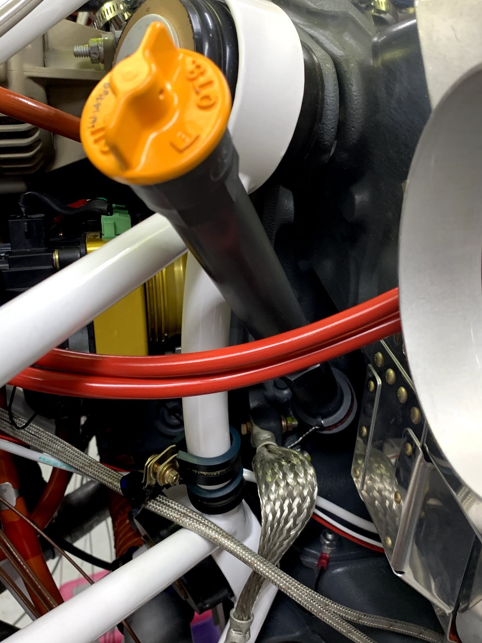
- installed oil filler tube (w/safety wire); installed front left and right baffles and tightened all screws/nuts
A little out of order, but here is the final wiring for the ANL fuses and shunts (pic below). One fuse per alternator, and one shunt per alternator, so I can read the current for either on the G3X EFIS. No need to read battery current - if I'm at the stage whereby I need to know how much current I'm drawing from the battery, then both my primary and secondary alternators have failed (unlikely), and I will be landing ASAP. Moreover, the EFIS screens have an IBBS (integrated backup battery system), and the G5 backup system has it's own 1 hr internal battery, so the chances of running out of juice are essentially nil. If all else fails, the engine will still run without any external power, and I can communicate via a handheld radio that I carry. I am a belt, suspenders, another belt, and a few more suspenders kind of guy:


No comments:
Post a Comment