- Riveted sub-panel assembly together
- installed instrument panel stand-offs and connector brackets; installed seal angles; installed upper fwd fuselage assembly to fuselage; temp. attached canopy hinge brackets; installed cowl pin retention bracket (prob. won’t use); installed wiring channel assembly; match and final-drilled fwd and aft canopy decks (both sides)
- deburred and dimpled (CS4) canopy decks; countersunk longerons; prosealed longeron-deck space; riveted instrument attach brackets to fwd decks; clecoed and riveted canopy decks to fuselage; riveted wiring channel and cable support; installed instrument panel attach plate; separated panel frame angles; deburred panel frame
- Machine countersunk holes in panel frame and panel flange doubler; riveted nutplates to panel frame; riveted panel angles to doubler and frame; clecoed panel frame assembly to fuselage
- fabricated a couple parts of avionics shelves/angles; another 2 hrs (not logged) spent cogitating over the placement of remote boxes, etc.
- cut another shelf for avionics; radiused/chamfered pivot block; drilled release mechanism; fabricated left and right release mechanism pushrods (pain in the ass!)
Masking the side skin, prior to filling gap with Proseal - sealant is used here to prevent water from intruding into the cabin:

Blind-riveted canopy side rails:
Another view of side rails:

Assembled and installed subpanel, and panel standoffs:

Countersinking panel frame assembly:

Attached and countersunk panel flange doubler:

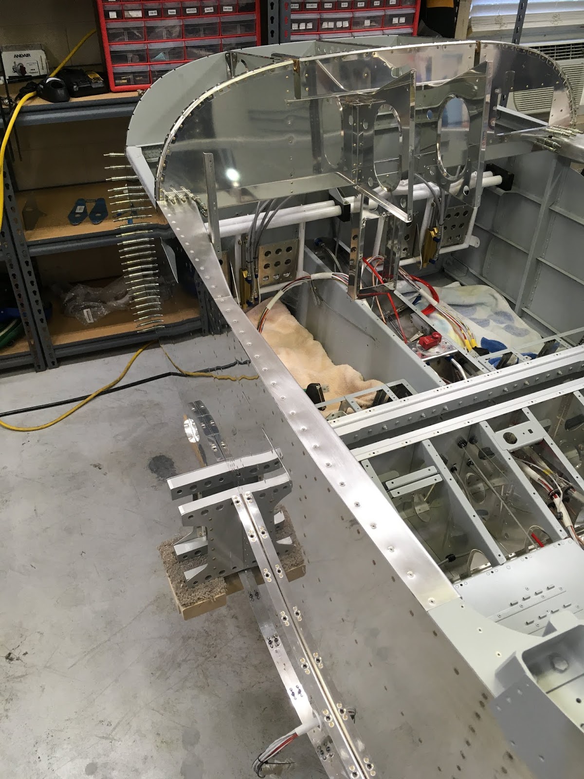
Panel frame, clecoed in place - will not rivet this in place, until I have a good idea what avionics panel shelves and rails I will need to construct, and also where I will place the AeroSport Products rudder trim knob. Right now, two shelves have been cut that fit between the panel frame and the subpanel, and two angle aluminum pieces have been cut that span the map box hole to firewall, where I will likely mount at least the remote Comm radio and IBBS avionics battery (thanks, Ken B., for these suggestions!):

Another view of the panel frame:

Note that the air vents, when clecoed in place, do not align at the area (left side of this photo) that will be glued using RTV to the inside side skins. I'm guessing I will have to bend the flange slightly to make it fit (2 bends - one to angle the aft portion of the aluminum more outboard and aft, and a second to realign the flange with the plastic part that attaches to the skin around the NACA duct).

The next three pictures depict a process that took me over 2.5hrs - fabricating the two canopy release pushrods from raw material AT6-058x3/8 tube. First, they are cut to size, which is easy. However, each needs a #12 hole drilled on each end, which goes through the tube. These are large holes relative to the width of the tube, and not only have to be centered but they also have to be (nearly) perfectly aligned with the holes on the opposite end of the tube. After that, channels are cut perpendicular to the drilled holes, and those too have to be as perfect as possible, otherwise the release mechanism will bind. This is what I did - first, center punch and #12 drill one hole in the end of one of the tubes - this hole just has to be centered. Next, temporarily attach an AN3 bolt, and use the flat part of the bolt head to help align where one should center punch the opposite end:

Below is the little jig I created to hold the tube - just a block of wood with a "V" channel that holds the tube, clamped in place. Note the axis of the bolt on the other side of the tube is used to align visually with the axis of the drill bit. Drill sloooowly, making tiny adjustments as necessary to ensure the hole is centered:

Once the holes have been drilled, you can start cutting the channels by first temporarily bolting at least two tubes together (I used three, the third being the leftover part of raw stock that I used to practice drilling #12 holes), and then drawing a center line on the middle tube either 5/8" or 7/8", depending on the side. Cut carefully along this line using a Dremel tool with a thin cutoff disc. Repeat for the other side. I then unbolted and transferred the center tube to a band saw, which enlarged the slots. I further enlarged the hole using a pneumatic mini sanding belt, until I could wedge my small file in the enlarged slot, and then did the final enlarging/shaping using the file, and sanded to remove burrs. Check the diameter of the slot with the appropriate part (i.e. the flat part of the release pin for the wider slot, and the flanges of WD-619 for the narrower slot):

Voila! Doesn't look like much, but it is a critical part of the canopy release mechanism ... now, hopefully nothing binds when I attach the release mechanism to the frame in a few days:

No comments:
Post a Comment