- drilled pedal bearing blocks; attached rudder pedals to fuselage; attached brake fluid reservoir (bolts and Proseal); attached Aircraft Specialty brake lines to pedals and gear brace (waiting for proseal to cure before installing last two lines on brake fluid reservoir); started two adel clamps that secure the rudder cable tubing
- finished installing all 4 adel clamps to secure rudder cable tubing; separated, deburred, primed, and painted rudder cable links; riveted cable guides to tunnel sides
- Finished attaching the brake lines
- Drilled flap torque arms; connected torque arms and flap crank to fuselage, and bolted (final torqued)
- installed flap actuator; safety-wired and tested actuator (9V batt)
- Installed the flap position sensor, including micro-molex pins in the corresponding connector shell
- Assembled left and right forward rib assemblies and hinge rib assemblies; trimmed sub-panel (including area for center stack); riveted channel assembly
Installed rudder/brake assembly:

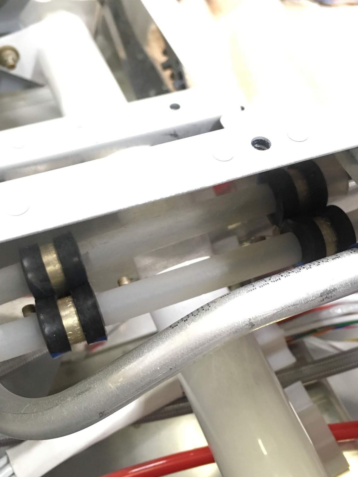
Installed brake lines (last two lines to reservoir were installed 3 days later - i.e., after proseal cured):

Brake lines going to gear:

The next step was to attach 4 adel clamps, which hold the rudder cable guides out of the way of the elevator stick control. This was a royal pain in the ass, but after I figured out how to do the first two (took over an hour), the next two were far simpler. First, install the clamp over the rudder cable guide. Then use a specific adel clamp tool shown below. Insert the awl into both holes in the adel clamp, and then clamp down with the modified vice grips. Finally, insert the bolt into the hole in the sheet metal, and start the nut. The forward nuts are difficult to start, so using a piece of tape to "stick" it to your finger may work.

For the aft clamps, the following tools were used in various forms. It's a tight fit, but you can ratchet each aft bolt/nut in a minute or two.

The forward clamps ... well ... let's just say someone at Van's has a sense of humor, and they're laughing at us. Once the nut is started, it is almost impossible to turn the nut more than a few degrees at a time, even with the right tool. Instead, I bent the closed end of a 1/4" wrench to 45degrees (shown below), and just shoved that onto the nut, jamming the tool in place. On the inboard side sits the bolt, and I used the flexible 90deg driver from DeWalt shown below with a 3/8" socket that fits 1/4" drives. Once I did that, I was able to tighten the bolt in about 10 seconds. It's tough for one person, but would be easy for 2 people to do:

Here are the adel clamps, installed on the left side:
Rudder pedal linkages, deburred, primed, and painted:

Forward Rudder guide blocks installed using CS4-x blind rivets:

Rudder cable links installed. The forward nut has been final-assembled with cotter pin. The aft nut is temporarily attached - I'll have to test the travel once I get to the hangar, attach the rudder, and have the pilot's seat in place. My legs are short, so the rudder pedals are in the aft-most position, and thus the rudder cables need to be attached to one of the forward-most holes.

Flap torque arm being drilled:

Torque arm lubed, inserted into the outboard and inboard bushing, and picture taken to ensure the rudder cable is above the torque arm:

Flap actuator attached and safety-wired in place:

Using a 9V battery to run the actuator up and down to confirm full travel and check for binding:

Flap position sensor, wired to a micro-molex connector:

Flap position sensor, bolted into place:

Forward rib assemblies assembled:

Center stack hole in the sub-panel and the stiffener were sanded down (on the hole's top surface, which is on the bottom in this pic) to prevent the GTN750 and audio panel from hitting the top of the sub-panel (thanks, Ken B., for alerting me to this!):

No comments:
Post a Comment