I completed a lot of avionics-related tasks during the past ~two weeks, including powering on the panel for the first time! Thanks to Sean M., I have a temporary ground power unit hooked to the aircraft, supplying about 14V (need to have between 13-15V to charge the LiFePO4 IBBS), and I can spend a couple hours at a time playing with the settings instead of only 10-15min with the ship's battery. Specifically, I did the following the past two weeks:
- finished tidying all wire bundles FWF; routed and terminated all grounds (34 in total) to “forest of tabs”
- wired voltage regulator for backup alternator; wired a few other loose wires; attached battery; attached two Comant COM antennae; attached (temporarily) transponder blade antenna
- routed RG400 and connected BNC male connectors to all 4 ends of the coax that goes to the Comant antennae
- fabricated and painted shelf for GPS antennae; routed RG400 for the main GPS antenna (from GTN750xi); ordered RG400 and female BNC to connect G3X "el cheapo" antenna
- tidied some of the avionics wires; routed main & G3X GPS antennae RG400 wires and mounted both antennae to shelf above baggage compartment; installed GTR20 (remote Com2) and voltage regulator for backup alternator to rails (fabricated previously); installed trickle charger harness to battery
- connected transponder and attached right avionics shelf; figured out LED strip light connections; troubleshot rocker switch backlighting issue (3 switches weren’t lit; bad wire crimp for two); wired G3X GPS antenna; wired GTN750xi Nav to Archer antenna (temp. install)
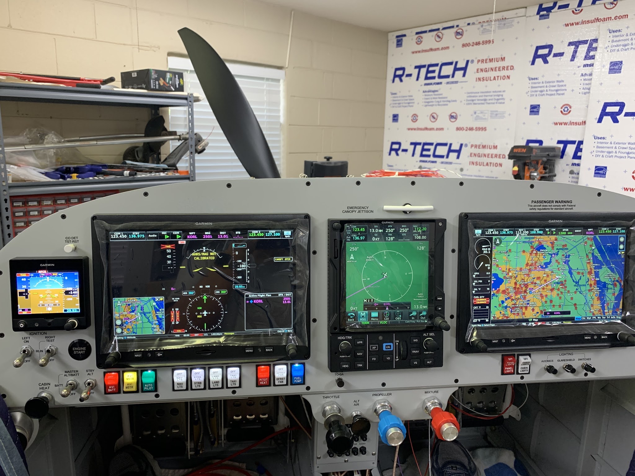
- attached power supply to airplane to test avionics without draining battery, and to charge the IBBS and G5 (since they supposedly need >=13.8V to charge - correction: 13-15V) ; Comms worked well in receive mode - used headset and separate handheld transceiver on 123.45MHz; programmed avionics (started)
- installed most components of the ELT (except head unit, since waiting for battery)
- attached labels to push/pull control knobs; attached canopy avionics wires to molex connector; routed and attached 2 wires to canopy open/closed switch; cut and attached glareshield edge trim; started planning SB for nosegear washer and cutout; cut LED light strip to size (plus one segment, according to Ken B.)
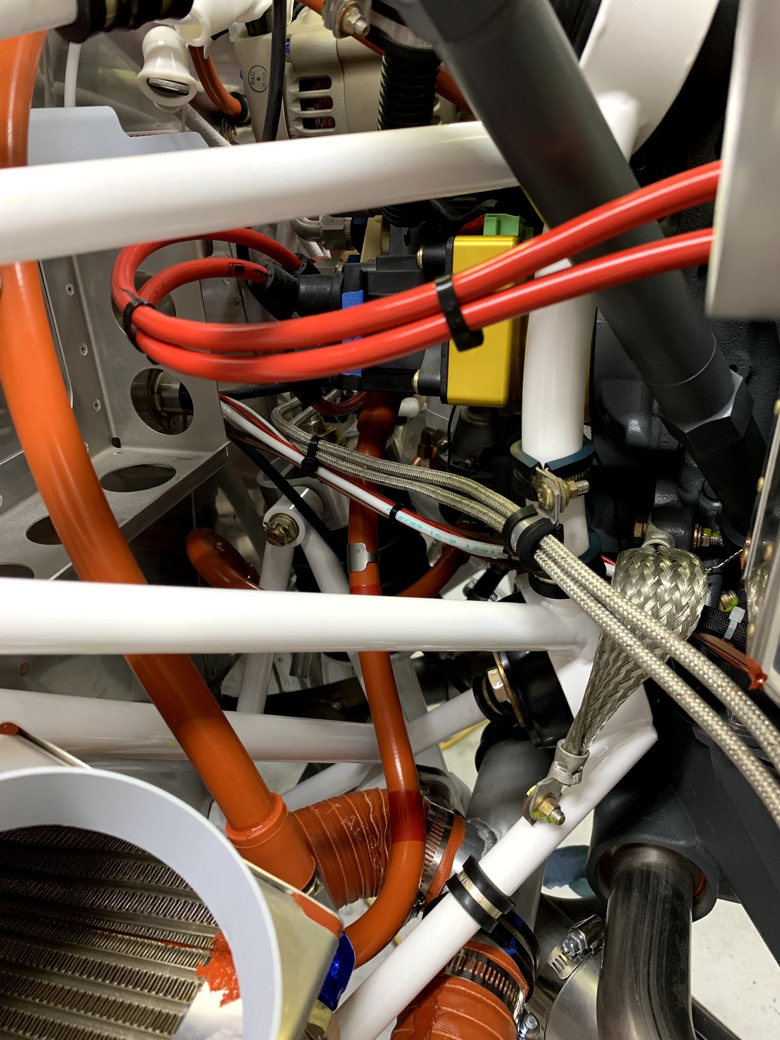
The next set of pics are the final tidying of FWF wires, hoses, cables, etc:
More tidying:
And more:
And, even more:
Cut, stripped, and crimped 1/4" fastons on to the ground wires:
Grounds connected to the Forest of Tabs grounding block:
Attached Comm antennae:
Crimped BNC connectors to RG400 and attached them to the Comm antennae:
Wired voltage regulator for backup alternator:
Attached transponder antenna to aft tail section:
Mounted voltage regulator on rails that extend between the subpanel and the horizontal firewall support:
Comm antenna, attached (I will be swapping out the 4 mounting screws, since these are one thread too short):
Fabricated shelf for GPS antennae, and installed both GPS antennae:
Mounted remote Com2 and installed wire bundle and RG400 to Com2 antenna:
Charging main ship's battery using a Battery Tender:
Pigtail connector that attaches to the battery for trickle- and float-charging:
Temporary Nav antenna (Archer) wired to Nav1 on the GTN750xi:
Transponder installed on shelf:
And the panel works! No smoke, no fire.
Another view - I love the look of the VFR charts on the left. The right has the engine and electrical monitors:
The power supply that I borrowed from my friend, Sean M. - Thanks, bud! I wired it to the ship using 8AWG wire. Works like a charm.
Installed ELT antenna:
Installed ELT annunciator on vertical stabilizer:
Attached and wired main ELT unit to aft deck on fuselage - ELT is still in the "off" position, but once the VS and HS have been installed (at the hangar), and everything is wired, I'll switch the ELT to "armed".
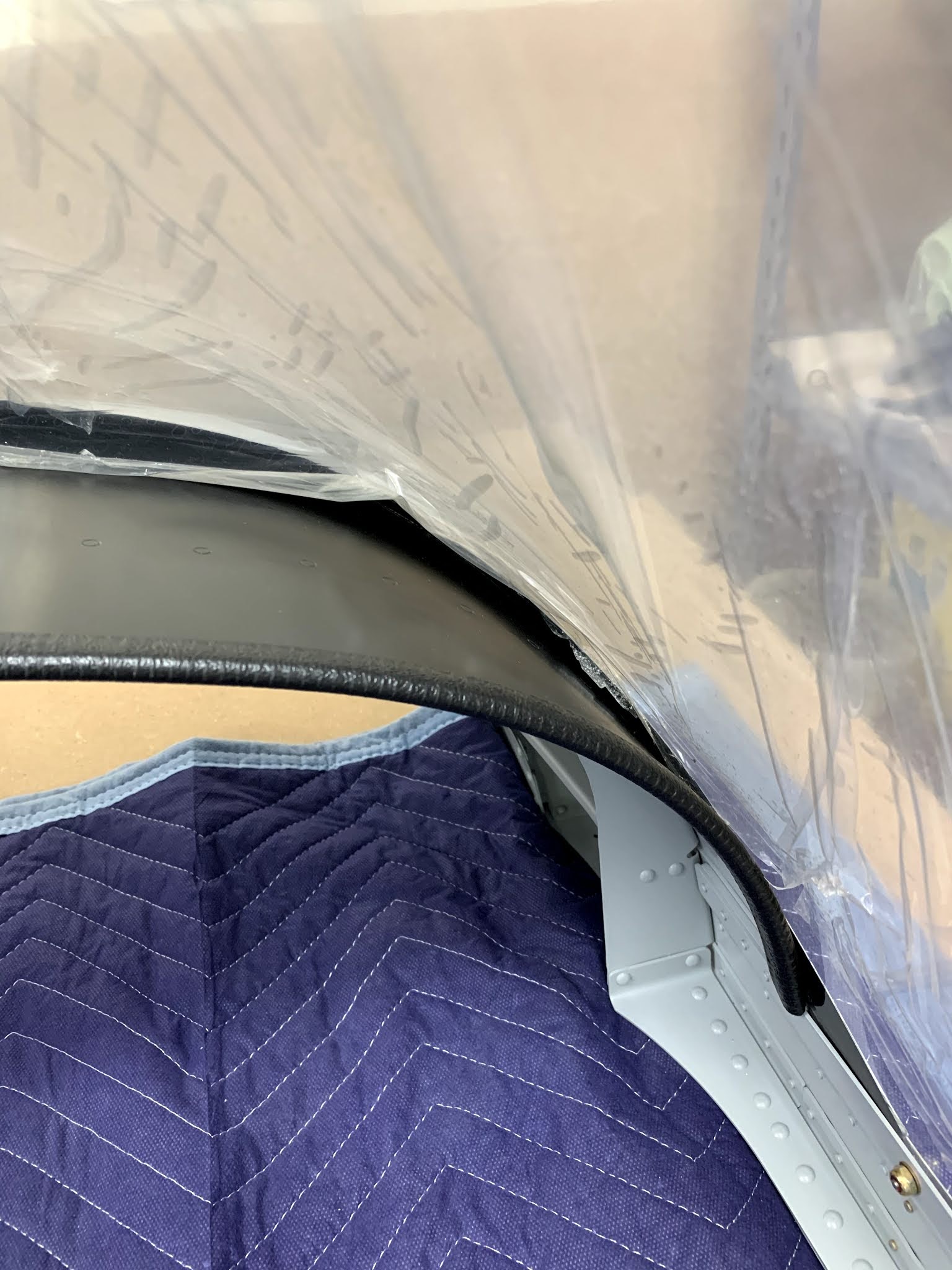
Wired the canopy switch (alerts on the G3X if canopy is open). I initially fed safety wire through the holes, which was a pain. Then I tried thinner safety wire, which was also a pain. Then I decided to just feed the two 22AWG wires from forward to aft, and it worked very well! Pro tip: start with very straight wire and go gently 2" forward, 1" back, repeat... until the wire pokes out the aft hole. To get the two wires through the oval hole shown in the pic, backthread very thin safety wire, tie around the black and red wires, and then just pull a loop through the oval hole. Voila! Took 5 minutes. Well, 5 minutes once I got the hang of it ...
Attached labels to push-pull controls. I know Vic Syracuse will want to see labels on EVERY control, switch, and input jack. This gets me one step closer to that goal.
Installed glaresheild edge trim:
Attached canopy open/close wire, red/white LED strip wires, glareshield dimmer wire (ground for both LED lights), and defog fan wires to Molex connector:


No comments:
Post a Comment