Monday, December 17, 2018

Section 10 - Aft Fuselage (VS match-drilling; top skin; EAA Tech Counselor)

I'm still slowly progressing through the last few pages of Section 10.  I have about 2 months and 3 pages left, so the next set of posts will be few and far between.  Note to self - order the fuselage kit well in advance of finishing the wing kit.

In the interim, I contacted a very nice and helpful EAA Tech Counselor (thanks, Joe F.!!), and brought him a representative example of my work (left elevator) as well as samples of the way that I'm currently dimpling and riveting, since they have changed slightly (see past posts).  Fortunately, I can say that my current dimpling and riveting techniques are on-par.  My earlier dimpling was a little shallow, likely due to dimpling with the vinyl still on the skins (I stopped that practice with the aft fuselage section, and now dimple with all vinyl removed).  Moreover, the overly cloudy look to the skins/rivets banged with the mushroom set might just have been schmutz accumulated on the polished head, which wasn't so polished anymore.  Joe used a Scotchbrite pad to clean the mushroom head surface, and it looks and rivets better.  Moreover, the Scotchbrite could remove the "cloudy" surface on the skins, revealing rivets and dimples that were just fine.  Phew - Build on!  Below are a few steps completed over the past ~week:

Attached the vertical stabilizer to the aft fuselage assembly with AN3 bolts and temporary nuts, to #12 match-drill two holes:


Saturday, December 8, 2018

Section 10 - Aft Fuselage (aft deck)

I've been progressing a bit slower these past two weeks, largely because I placed my order for the wing kit and found the ship date is not until the end of January.  Since I'm not doing the tailfins attach step (Section 11) until I join the aft fuselage to the mid fuselage, nor do I yet have the skills to do the fiberglass work (Section 12; EAA SportAir Workshop will likely be in May 2019), I essentially have only a few more pages of the Empennage kit to complete over the next 7 weeks.  After I finish Section 10, I'll reorganize the workshop, hang some of the completed parts on the wall, and prepare to receive the wing kit.

A fellow VAF member took a look at some of my blog pictures, and spoke with me about a few concerns he had about some of my dimples (thanks Henry!).  I think I'm dimpling much better (see my post a few weeks ago about removing the vinyl, proper tightness of the dimple dies, etc), and two-dimensional pictures can sometimes be deceiving to the viewer.  However, I'm far too much of a novice to think that what I am doing is completely correct ... so, I'll be calling the Big Guns (an EAA Tech Counselor) to take a look sometime during the next few weeks.  In the meantime, I completed the aft deck (Page 10-27), which took a lot longer than I had anticipated.

I decided to prime all aft deck parts prior to assembly - although three of these parts are alclad, I deburred and scratched them more than usual and thought they might benefit from a coat of primer.  I was itching to paint something anyway ...


Thursday, November 29, 2018

Section 10 - Aft Fuselage (bushings; teflon blocks; rudder cables; static ports/lines; antennae wires)

Finished a few small tasks since the last post.  I decide to use the Cleaveland Tools Static Port and tubing kit instead of the stock Van's kit - the lines and connectors are beefier, and the ports are robust (not just two modified blind rivets).

Inside view of one of the two static ports, cold-welded to the inside of the side skin:


Friday, November 23, 2018

Section 10 - Aft Fuselage (finished riveting side skins; rudder stops; angle brackets; nutplates)

During this past week, I spent the majority of my time on page 10-19, which involves riveting the side skins to the longerons, j-stiffeners, bulkheads, and bottom skins.  I could buck or squeeze most of the rivets by myself ... except for about 140 rivets that attached the curved part of the side skins to the bottom skins.  My wife volunteered her time and skill, and we made quick work of it.  It was the first time she has bucked a rivet - I think I'll be using her newfound talent more in the future.

Squeezed the rivets along the longerons:


Saturday, November 17, 2018

Section 10 - Aft Fuselage (completed SB-18-09-17; attached R side; riveted skins to bulkheads)

Due to work (grant deadline looming) and extra extracurricular activities for the kids, I had not stepped foot in the shop for 5 days. However, with the wife and kids visiting grandparents in south Florida, I had plenty of time to catch up today.  First, I completed the service bulletin (SB-18-09-17), since it was easier for me to rivet stiffeners to the bottom skin when the right skin was not yet attached.  After completing the SB, I proceeded to attach the right j-stiffeners (A and B), the right longeron, and both angle stiffeners.  I then modified the aft bottom skin, dimpled where necessary, riveted the aft bottom skin to the aft-most (F-01412) bulkhead, and wedged the two in the aft portion of the aft fuselage assembly.  I then started to rivet the F-01411 bulkhead (second from aft) to the aft bottom skin ... and then I realized I had been in the workshop for nearly 7 hrs without food and without stopping. Then beer called ...

Completed SB, outside view (doubler attached to bottom skin):


Sunday, November 11, 2018

Section 10 - Aft Fuselage (bottom skin; wiring harness; side skin; started assembling aft fuselage)

I made a decent amount of progress this weekend after a total of about 15 hrs in the workshop. Following last week's fitting of the frontmost bulkheads, I dimpled all holes in the bottom skin, except for those called out in the Service Bulletin (SB-18-09-17).  This optional SB adds doublers and stiffeners to strengthen the section of the skin that attaches to the F-01408 bulkhead (2nd from front), which is prone to cracks.


Sunday, November 4, 2018

Section 10 - Aft Fuselage (several more bulkheads; bellcrank rib assembly)

A decent amount of progress was made since the last post - deburred and riveted the 3rd, 4th and 5th bulkheads (front 3), primed several parts used for the bellcrank rib assembly (as well as future parts of the build), and attached the large (forward-most) bulkhead to the assembly. Having a large structure on the two sawhorses was very satisfying ... this puppy is starting to take the shape of the aft fuselage.

Riveted the 3rd bulkhead to the doublers and horizontal stabilizer attach bars:


Friday, November 2, 2018

Section 10 - Aft Fuselage (aft bulkheads and attach bars)

Continued to (slowly) progress through the steps of assembling the 2 rear-most bulkheads and associated attach bars and tie-down bracket, as well as starting the 3rd bulkhead from the rear. I'm starting to see the light at the end of the empennage kit tunnel - it is nearly time to order the wing kit ... probably by the end of November to have it delivered ~mid-January.

Clecoed and then final-drilled the second bulkhead (2 pieces) from the aft section to the horizontal stabilizer attach bars:


Wednesday, October 31, 2018

Section 10 - Aft. Fuselage (bulkheads; tie-down bracket priming)

Continued working on parts of the aft fuselage, including the rudder stops, horizontal stabilizer attach bar, rear bulkheads, and town-down bracket.  Since I fabricated/deburred the alclad parts enough to scratch them substantially, I decided to prime those with the non-alclad parts.

Countersunk rudder stops.  The regular countersink cage tool didn't fit due to the flange, so I used a countersink bit-extender (without a cage) and tried to carefully keep an even countersink:


Friday, October 26, 2018

Section 10 - Aft Fuselage (cable guides; j-stiffeners; longerons; attach bar; rudder stops)

A couple days of separating parts, deburring the edges, and other initial tasks for the fuselage.  A few of the parts completed so far are below (longer j-stiffeners not shown):


Tuesday, October 23, 2018

Section 9 - Elevators (wired trim tab motor; rolled left leading edge; fabricated counterbalances)

The elevators have (finally) been completed! The pictures and tasks below are from several days during the past ~week.

5 wires emanate from the trim tab motor, and need to be stripped, crimped into male micro-fit Molex pins, and then inserted into the black Molex housing shown below. Easy enough task? Not without the right tools.  First, I ordered a crimper that another blogger recommended - it is cheap, and really not great quality; however, for these 5 crimps, it should (and did) work fine. Then I tried to strip the 5 wires with my trusty old (emphasis on OLD - 35 years at least) wire strippers that my dad passed down to me. No dice - they were too dull to do the job on these fine 26AWG wires.  Next, I ordered a Chinese knock-off automatic wire stripper ... which is STILL in the mail, on the slow-boat from China.  Since I wanted to complete the elevators this week, I ordered a very high quality wire stripper (Ideal Stripmaster; 16-26AWG) that came the next day, and made quick work of stripping those 5 wires.  That's it - no more crappy tools!

A word about micro-fit Molex connectors:  Several folks on the VAF forums have made a big deal out of these connectors, but they are actually quite easy (if your eyesight is good - they are tiny). Strip about 1/8" of the wire; insert the metal pin into the crimper, making sure that the back end is flush with the crimper; insert the wire such that only about 1/16" of the insulation sticks into the pin - i.e. just enough so the first band crimps the insulation and the second band crimps the wire; and, then crimp firmly (but not too hard); finally, tug the wire to make sure the connection is secure.  Next, note that the pin's cross-section is a "U" and also note that inside each hole of the 6-pin molex housing has a little tab on one side.  That tab slides between the "U" of the metal pin.  You may or may not hear a click when it fully inserts; pull to make sure the pin seated in the black housing, and that's it!  It only goes in one way.  Others have just tried rotating it 90deg when it doesn't work ... but why guess? Take a look inside the housing to locate the little tabs, and then orient your pins to match.


Tuesday, October 16, 2018

Section 9 - Elevators (riveted right trailing edge; rolled/riveted right leading edge)

After letting the 6 right trailing edge foam ribs cure for 3 days following adhering with proseal, I double-blind riveted the 51 rivets in the trailing edge, riveted the remaining rivets in the tip rib and inboard rib, and then rolled and riveted the leading edge of the right elevator. Just as with the rudder, rolling the leading edge is an exercise in patience - two-thirds with a 1" PVC pipe duct-taped to the entire length (see section 5.9), and then the rest of the way slowly massaging it by hand.  The two skins must overlap to reduce/eliminate stress on the rivets; once they do overlap, blind-riveting them together was a snap ... and a great sense of accomplishment.

Straight, right trailing edge (top view, machined rivet heads):


Saturday, October 13, 2018

Section 9 - Elevators (proseal foam ribs to elevators and tabs; rivet trailing edge; trim tab motor)

Productive week in the workshop - prosealed all foam ribs to the trailing skins of each elevator and trim tab; used VHB tape to attach all trailing edge wedges (3); squeeze-riveted the trailing edge of the left elevator and trim tab; pop-riveted the closeout tabs for the left elevator and trim tab; and, started working on the trim tab motor. I had to stop since my very old wire strippers were inadequate, and my new ones are on the slow boat from China.  Damn, I should have bought those from Cleaveland Aircraft Tool - they would be here by now. That's what I get for trying to save $4.

Proseal is a mess; and this particular formulation hardens quickly, so you have to work fast ... thus no pics of the foam ribs slathered in the dark grayish goo.  Left elevator is shown here.  Note that for all trailing edges, I modified the process only slightly - attach VHB tape to both sides of the trailing edge wedge, let cure for about an hour, stick to the lower skin, proseal the foam ribs in place, close the skins, and remove the VHB protective backing and stick wedge to upper skin (instructions has you doing this after proseal curing).  Worked well, and it was easier to remove the tape's backing.


Sunday, October 7, 2018

Section 9 - Elevators (riveting skins to spars, and other misc. riveting)

This will be a long entry, because of a very productive Friday night and all-day Saturday ... most of it spent riveting many pieces together.  A "special bucking bar," used only for the RV-14 and RV-10 elevator to attach the bottom of the left elevator skin and top of the right elevator skin to their corresponding rear spar with AN426AD3-3.5 rivets, was used today ... and likely will never be used again for this build.  I wish I had taken pictures of bucking those rivets, but I spent so much of my mental energy trying not to F it up - one has to position the elevators on a shim (I used cardboard), and the edge of the elevator is then placed about 3" inward of the edge of the table.  The foot-long bucking bar uses the edge of the table as a fulcrum, and thus you press down on the back end of the bar, bucking upward into the rear spar under the skin.  Counterpressure pushing from the flat rivet set will set the rivet.  Anyway, here are the pics from the last two days:

Midway through riveting the trim tab motor housing doubler:


Thursday, October 4, 2018

Section 9 - Elevators (riveting two skins to rear spars and ribs)

Slow yet steady progress on the elevators this week.  During the last few days, I riveted the left and right spars to 12 rib halves (not shown; the other half goes on the respective skins in a subsequent step) and 3 shear clips (2 for left elevator, 1 for right elevator). Shown below are the first steps to attach the skins to the rear spars and rib halves.

Clecoed then riveted top left skin to left rear spar and front part of trim tab hinge:


Sunday, September 30, 2018

Section 9 - Elevators (riveting items to front spars)

I had a very productive Sunday, consisting mostly of riveting.  Specifically, I riveted the tip ribs to each other and then to the front spar; hinge reinforcement plates, nutplates and root ribs to the front spar; counterbalance skins to tip ribs; and, elevator horns to the root ribs and front spar.  Also installed a bushing for what I assume will serve as a conduit for wires that lead to the trim tab motor.


Friday, September 28, 2018

Section 9 - Elevators (riveting trim tab spar and horn; scuffing elevators for foam ribs)

The beginning of this week didn't have much to report - just riveting the trim tab spar and horns to the trim tab, as well as scuffing all 4 skins of the elevators and 2 rear spars to accept the prosealed foam ribs.  I hope to accomplish more this weekend, when I have a little more time (busy week at work and with after-school kid activities).

Riveting of trim tab spar and horns:


Sunday, September 23, 2018

Section 9 - Elevators (trim tab; priming)

Today's task was to fabricate the trim tab to the point where I have to Proseal the foam ribs to the skins/spar ... but I'll actually hold, so I can do that part when I glue the foam ribs to the left elevator (i.e. don't waste the Proseal).  I was almost to the point of riveting the trim tab horns, until I realized I wanted/needed to prime them prior to installation.  So I ended up priming all the other parts that either were non alclad, or that I scuffed so much during fabrication that the alonized coating had worn off.

Most of the trim tab parts (there's not a lot to it) - not shown are one foam rib, the small trim tab horns, and the aft hinge:


Saturday, September 22, 2018

Section 9 - Elevators (deburring, match-drilling, and a bunch of other tasks)

A lot of small, but (seemingly) important tasks happened since the last update, including bending close-out tabs on left skins, cutting right rear spar, drilling the 5/8" and 3/8" holes in left spar, clecoing (and then unclecoing) ribs and skins, match-drilling #30 and #40 holes as requires, and lots and lots of deburring of edges and all holes.  Oy.  Did I mention deburring?  Finally, I dimpled the ribs, spars, trim motor access doubler, shear clip, etc., fashioned the trim tab horns and pushrod, countersunk the trailing edges and rear spars, and riveted nutplates. All this and more took about 21 hrs. I didn't take too many pictures of all these steps, but here are a few:

A couple holes needed this little bad boy (90deg angle drill attachment from Cleaveland Aircraft Tools):


Monday, September 10, 2018

Section 9 - Elevators (initial prep; ribs; foam ribs; clecoing main structures)

Gathered all of the parts necessary for this section, which will build the elevators.  It seems that building the elevators will be as involved as the three sections that preceded it combined, so I'm sure this section will take me quite a bit of time.  Below are the smaller parts; not shown are the elevator skins, trim tab skins, lead weights, elevator horns, various hardware, and trim tab motor.


Sunday, September 2, 2018

Section 8 - Horizontal Stabilizer (riveting skins to front/rear spars, ribs, & stringers)

A few days have passed, but on-and-off during that time I made 4 cradles to hold the horizontal stabilizer, using plywood scavenged from the top of the empennage crate as well a few feet of 1" angle aluminum I bought from Van's last month "just in case I needed it."  Then I riveted the remaining 3 nose ribs per side. The two inner nose ribs per side, which required bucking at the very forward of the skins, required quite a long monkey-arm to reach, as well as riveting in spurts by Braille (and visually checking, of course). Then, I found that the opposite side required learning how to rivet left-handed (i.e., gun in left, bucking bar in right). Surprisingly, not a lot of swearing, since I anticipated those ribs would be pains in the butt. Part of the reason I could rivet them at all is because of the tungsten bucking bar I got from Cleaveland Tool, which has a very high density; it's shit-ton expensive, but WELL worth the price paid. All surfaces can be used to buck rivets, which helps get it into some tight spots.

The most gratifying part of this section of the build was dropping the skeleton (front spar assembly, ribs, stringers) into the skins and clecoing the whole mess together, because NOW it looks very close to the final product:


Tuesday, August 28, 2018

Section 8 - Horizontal Stabilizer (countersinking/dimpling; substructure)

Lots of progress the last couple of days - these myriad parts are starting to look like a horizontal stabilizer ... well, the skeleton anyway.  Much of the work has been deburring edges and holes ... a thankless but necessary task that took a half dozen hours.  Not shown, dimpling the ribs and skins, a task I very much enjoy (using the DRDT-2 is therapeutic). Below are a few pics from this midpoint stage in assembling the H.S.

Countersinking a couple hundred holes on each side of the front and rear spars, and stringers (rear spare shown here). Aluminum shavings/filings everywhere!


Wednesday, August 22, 2018

Section 8 - Horizontal Stabilizer (initial work, front and rear spars)

Starting with the Horizontal Stabilizer, I am priming ONLY non-alclad parts, since the pure aluminum coating on the alclad parts acts to prevent corrosion.  I estimate that this will save about 10lbs in weight overall, as compared with priming all non-skin internal parts, which was my original modus operandi.

Rear spar with 4 of 5 brackets clecoed (this is the only pic I currently have of the rear-spar - it is currently riveted and sitting awaiting assembly with the ribs, stringers, etc.):


Sunday, August 12, 2018

Section 7 - Rudder (riveting everything together)

Lots accomplished today, much of which was riveting.  This post will be mostly pictures, with only a few words, since I'm pooped from almost 8 hrs in the workshop.  All the parts preparation the last week or so made today just knocking out the riveting tasks one-by-one.

Back-riveted stiffeners to rudder skins and and blind-riveted stiffener clips to right rudder stiffeners:


Friday, August 10, 2018

Section 7 - Rudder (new bench/shelf; trailing edge; priming)

I needed a little more storage for the large flat and odd-shaped  pieces in the empennage kit (the floor wasn't working), so a fellow builder (Ken B.) recommended 2x4basics (Amazon) to create a 4'x8' bench/shelf.  He uses this setup for the wings (large) in lieu of the EAA workbenches.  I'm using it for storage, at least for now - thanks for the suggestion, Ken.


Saturday, August 4, 2018

Section 7 - Rudder (trimming; initial assembly; drilling trailing wedge)

The rudder is making the vertical stabilizer seem like child's play.  Lots of little parts that all need to be separated and trimmed down to their final shapes.  Skins are VERY thin (0.016") and feel like they will bend/break when I move them around.  Tons of rivets in the skin as well as lots of LP4-3 (and other) blind rivets to zip the entire assembly together.  Amazing engineering though; I like the lead weight used as a counter balance.  For those of you, whom have flown an RV, that smooth feel of the control surfaces is due in large part to well-matched counterweights.

A few pictures from this part of the build are below.


Saturday, July 28, 2018

Section 6 - Vertical Stabilizer (finished! ... well, almost)

Over the last couple of days, I plowed through riveting the doublers and hinges to the spars, the ribs to the front spar, the skin to the assembly, and the rear spar to the final assembly.  I had to drill out a few bad rivets, but otherwise, it was fairly straightforward.  BUT, there is ONE darn rivet that even my thin tungsten bucking bar, on its side, can't buck (FYI, it's the forward-most rivet where the skin attaches to the top spar). I guess I'll be putting in an order for a thin yoke with Cleaveland Aircraft Tool!

Aside from that one rivet, the rest of Section 6 is complete.  In total, it took 31.1 hrs to complete a whopping 5 pages ... and that doesn't count most of the reading, planning, and cogitation!  This must be a slow-poke record.  Well, I'm taking my time.  Here are a few pics as I riveted everything together:

The pneumatic squeezer, with adjustable set to rivet, made quick work of the AN470AD4-sized rivets ... now, I just wish it was that easy to use the squeezer on the skin-to-spar AN426 rivets!


Tuesday, July 24, 2018

Section 6 - Vertical Stabilizer (priming)

I'm now at the stage of cleaning/prepping and PRIMING the metal - a topic that has been the subject of many highly opinionated forum posts.  It seems there are as many ways to prep and prime as there are people who have completed RVs.  From reading WAY too many of those posts, I'll summarize what I feel to be the best balance of quality, durability, weight, cost, ease and efficiency.

After all metalwork has been accomplished, including dimpling and countersinking (but, of course, BEFORE riveting anything), I cleaned the surface of all pieces to be primed with 100% acetone, using blue nitrile gloves to prevent oils from my skin to contact the surface and prevent the primer from sticking.  I decided to prime the following: all 4 ribs, both spars, the two doublers, and the internal rivet lines in the skin (not the outside, and NOT the entire internal surface skin - it already has a nice protection from the pure-aluminum alclad coating). I am NOT priming the 6 steel hinge brackets, since they came from Van's powdercoated (but, after match- and final-drilling, I did add a little 3-in-1 protective oil to any exposed steel surface, to prevent rust).

After acetone cleaning the surface, I used a Scotchbrite maroon pad to scuff any surface to be primed - for the ribs, spars, and doublers, I scuffed every surface. For the skins, I scuffed only the internal rivet lines. I then cleaned the surfaces well with Kleenstrip Prep-ALL, let dry, and primed with SEM #39683 self-etching gray primer (aerosol can) - it is expensive (about $21 per 15.5oz. can), but it is easy to apply (no HVLP gun needed!), dries quickly, and is tough after it has cured.  I bought a little spray can trigger handle to ease application of the primer, and primed until I couldn't see metal (~3 light passes or so), waited 5 minutes, flipped the pieces and primed the other side (the skin was primed standing vertically). I plan on letting the primer cure at least 2 days before riveting.  Here are most of the pieces, drying/curing after priming the second side:


Friday, July 20, 2018

Section 6 - Vertical Stabilizer (initial assembly; mock-up; deburring)

As most of your know, sections 1-5 in the plans are background reading - some of this is covered if you take an EAA SportAir workshop, but I highly recommend reading every word.  Twice.

So, the Vertical Stabilizer (VS) is the first "real" part of the RV-14A that I'll be tackling, and having skimmed the plans, it looks like it should be one of the more straightforward sections.  Good thing Van's starts out with the VS - some of the other sections would be far too daunting (kudos to the early builders, who had to start with the wing kit first, since the empennage kit wasn't available back then).

Building an aircraft, even one as supposedly straightforward as a Van's RV-14A, is a lesson in humility. Although I read ahead in the plans, I did not realize that my initial tool purchase should have also included the following, which I bought recently:   small-diameter female dimple dies (I now have both the 3/32" and 1/8" sizes, just in case) ... I need those soon to dimple the ribs in the vertical stabilizer, since the clearances are less than the standard dimple dies. After a nice exchange with Annette at Cleaveland Aircraft Tools, I purchased a slew of other tools she recommended:  a special bucking bar (long; used for the empennage somewhere ... works on RV-14s and RV-10s), a trailing edge drill jig, a special #40 countersink,  an angled male dimple die (used on one of the trailing edges), a 12" back rivet set with a back riveting bucking bar (beefy!), a substructure dimple die set (dimples the spars/ribs/etc. a little deeper, so the skins mate better), a tank dimple die set (dimples a little deeper, to permit the Proseal to seep into the rivet pocket), and a few other tools that I'll discuss in later posts.  Again, I can't speak highly enough about Annette at Cleaveland Aircraft Tool - a level of customer service I'd imagine folks had in the '50s and '60s, but that I've never experienced before.

At the pace I'm going, a 5 year build sounds about right - the first day, it took me 2.5 hours to go through 
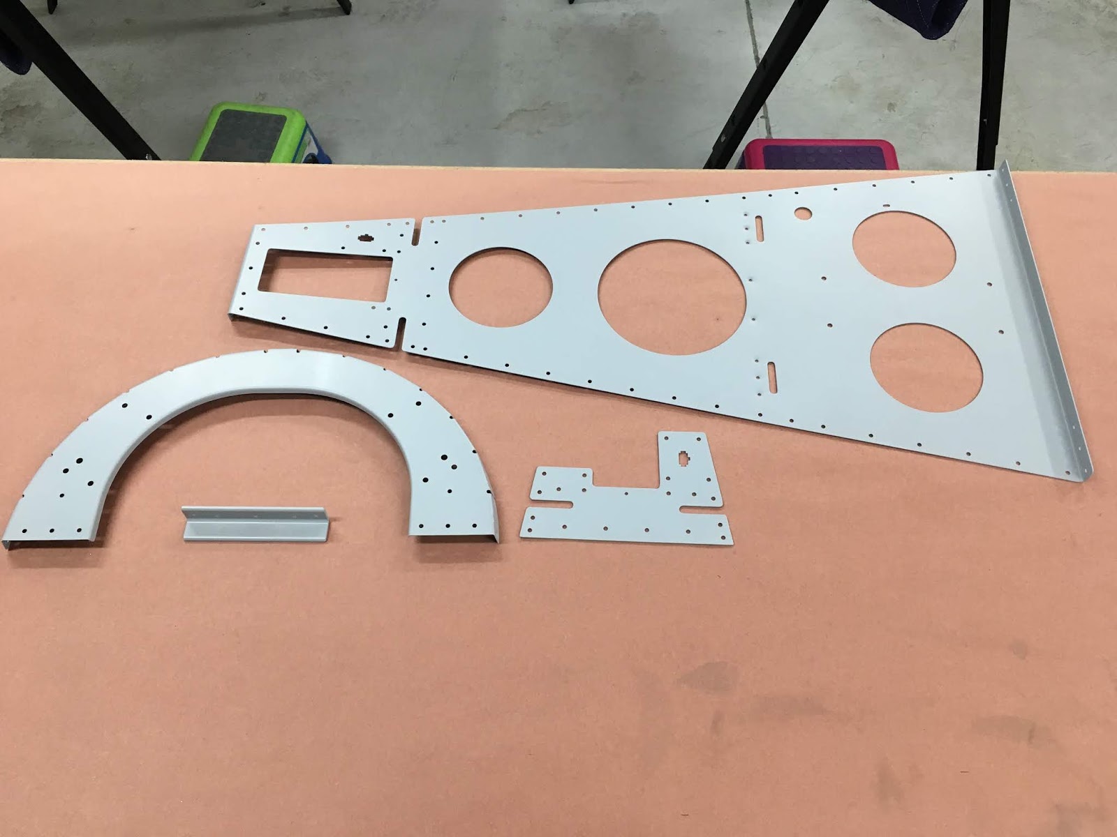
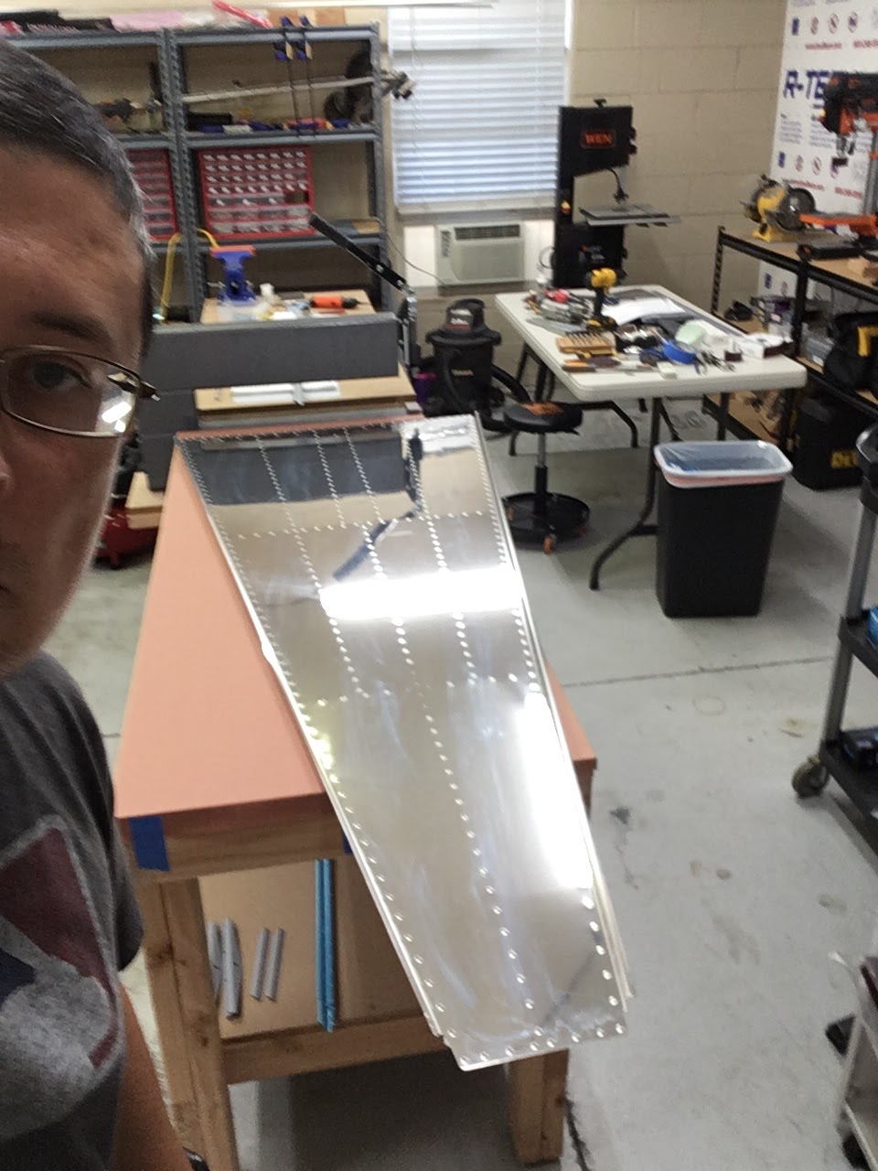
only the first page of Section 6.  I'm (finally?) on page 3 now, and can start to see the semblance of a real aircraft part.  I clecoed the 4 rib sections to the front and rear spars, clecoed the skin to that aggregate spar assembly, final- and match-drilled all the holes, and voila!  Progress:


Friday, July 13, 2018

Empennage arrived!

The RV-14A empennage arrived today, via XPO Logistics.  Although there was minor damage to one end of the crate, fortunately it does not appear that any parts were damaged.  After ~6 hrs of unpacking and inventory, I am still not finished.  There are a TON of rivets and other hardware bits - no wonder constructing an RV-14A takes several years (for most of us mortals).

So far, I'm only missing a few blind/pop rivets, and one of the fiberglass pieces has a ~3/4" crack (likely prior to shipment) - I'll be asking for replacements.  Otherwise, an impressive crating/packing job - it is almost an art form how the pieces fit together.  Here are a few pics from today:

After most of the sub-kits have been removed:


Wednesday, July 11, 2018

Cleaveland Tool shipment arrives; DRDT-2 shelf constructed

Oh happy day - on July 5th, a large shipment of aircraft tools arrived from Cleaveland Tool (thanks for the excellent packing job, Annette!) and a couple days later, the DRDT-2 arrived. I started with the base RV-14 toolkit, and then substituted (e.g. DRDT-2 for the c-frame tool) and added from there.  The quality of all the tools appears excellent. I decided to go with both  2X (Sioux brand) and 3X (Cleaveland brand) rivet guns, since I like the lighter touch of the Sioux 2X for most -3 and -4 rivets, but need the 3X gun for the bigger boys. The Sioux air drill is a lightweight dream. I also decided to get a pneumatic pop rivet puller and a pneumatic squeezer, both of which should save my hands a bit.  I like manually placing my own clecos - for now - so a pneumatic cleco gun is not (yet) on my radar. The tungsten bucking bar is really quite amazing to hold.  The density of tungsten is about 2.5x that of steel, so this 1.7lb little guy should be able to fit into places that the larger, steel, footed bucking bar (2.2lb) can't reach. I'm looking forward to using it.

As many of you know, the DRDT-2 seems to be the premium dimpling c-frame, and many builders have designed separate workbenches for their use.  I went the route of designing a small shelf that fits nicely between the two workbenches, to which I bolted the DRDT-2.  The height of the shelf is such that the lower dimple die will be at the same level as the two workbenches, and the shelf can slide back about 40% to accommodate different aluminum sheet widths.  Removable clamps secure the two tables together, and the shelf to the tables.  Here is the final product, sans dimple dies:


Wednesday, July 4, 2018

EAA Workbenches completed!

The plans worked very well, and are found here and here.  Note one error on the PDF plans:  on the first page, cuts in fourteen 2x4s and one 4x8' MDF are shown; however, the MDF cuts should be two of each of the 24x60" and 24x50" pieces.  The plans also state using 1/2" plywood for the shelf, but at Home Depot (at least in my town), 1/2" MDF was cheaper, and looks better, so I went with that.  3/4" MDF would work as well.  Regardless, these are two VERY stable tables, and will be excellent platforms on which to build an airplane.  Kudos to EAA Chapter 1000 for designing such nice workbenches!

Here are the near-final workbenches:


Workshop construction and Empennage kit ordered

Welcome to my Builder's Log for my RV-14A!  I have visited/drooled/lurked on Vans Airforce for several months, and after reading many of your posts, I decided to take the EAA SportAir Vans-specific course in sheetmetal construction, and then pull the trigger on purchasing tools (Cleaveland Tools) and finally the RV-14A Empennage Kit from Vans!  The major aircraft tools arrive tomorrow, and the empennage kit should be here late next week.

For now, I'm setting up my workshop, which will occupy just over 2 bays of our garage.  Since it is hot here in central Florida (!), and my wife still wants to use her side of the garage, I needed to construct an insulated wall between where my wife parks and where I have cordoned off an A/C zone to keep temps reasonable to work (for me, that's around 80F).

Wall construction:   Metal studs/tracks were far easier to manipulate, and can be easily trimmed with aviation snips.  The final wall will be shown in a later post.