Clecoed the front-most two bulkheads to the bottom skin, and started riveting:


I wasn't happy with the way the rivets were sitting in the holes, prior to using a flush set to rivet. They are "good enough" meaning that they don't sit proud after riveting, but they could be a little better. There seems to be something amiss with the way I am dimpling thicker skins. I noticed this on several of the prior sections, but it wasn't as pronounced as for the bottom skin. I use a DRDT-2 to squeeze the dimples, which the forums have indicated does not leave as crisp a dimple as a standard C-frame dimpler, which are set with the crisp whack of a mallet. I read somewhere on VAF that there is a negligible difference between dimpling with or without the blue vinyl protective covering still on (someone determined this empirically, and the difference was at most a couple thousandths of an inch). I've been leaving the vinyl on since many folks do that, esp. those with C-frame dimplers. However, while the force of driving a dimple with a mallet may be enough to overcome the vinyl's thickness, squeezing a dimple may press the vinyl into a shape that interferes with the final shape of a proper dimple.
I therefore performed a little experiment with a couple 0.025" coupons (same thickness as the aft fuselage skins). For both, I drilled four #40 holes, deburred, and proceeded to dimple with both sides having vinyl, the male side having vinyl but the female side bare aluminum, the reverse of that, and then both sides bare. The best of the 4 was the bare aluminum. I then set the dimpler to 4 different levels of "snugness" to see if cranking on those dimples will help or hurt. The first level had the dimple dies barely touching; the second was snug (couldn't turn dimpling sets when DRDT-2 was fully depressed), the third was snug + 1/4 turn; and the 4th was sung + 1/2 turn. The snug + 1/4 turn on bare metal provided the best dimple. SO, from now on I will be dimpling without vinyl, and with this snugness setting - the latter of which I was already doing. Here are those coupons:

the other side of the coupons:

Voila, the bottom skin was riveted to a few stiffeners and the front two bulkheads (upside down):

Another view:

Deburred edges, deburred holes, and dimpled the right side skin (left was done as well; but, no pics):

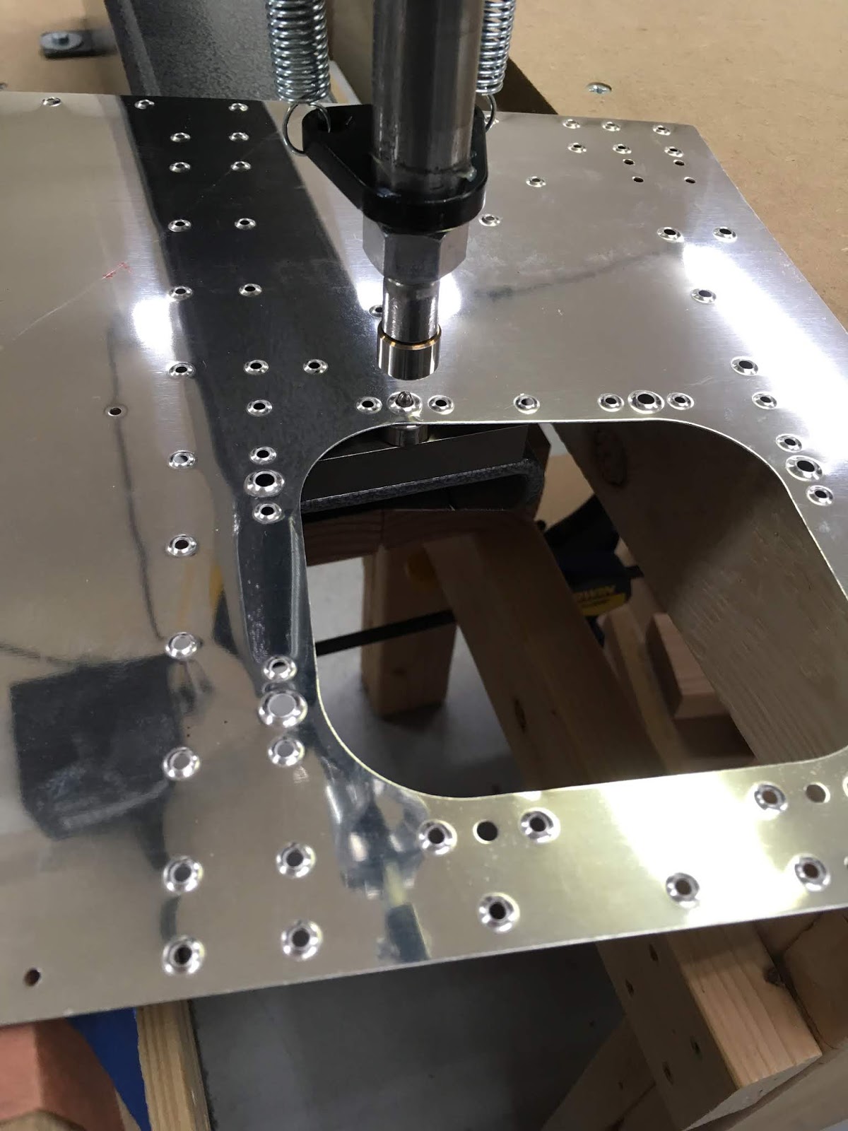
DRDT-2 dimpler in action:

I opted to dimple the access port nutplates, to have a nicer, flush look when completed:
The left "A" and "B" J-channel stiffeners and the left longeron are loosely attached - note the structure is still upside-down:

another view:

Starting to unravel all the wires in the WH-00057 harness. Routing all those wires was not easy, but if done methodically, it eventually all fits in the J-channels. Make sure to keep all the cable "zip" ties loose, and only partially tighten the J-channel ones AFTER installing the "phone cable" (for the ELT). NOTE, the two white wires that return from the C409P molex connector are TOO SHORT. This has been a known problem for at least 4 years, according to VAF. Oh well - I'll just contact them to get a few extra pieces of wire, a couple butt-splices, and a couple molex connector pins. Another option would be to reroute them through the center j-channel, but that's where an antenna wire goes, and I don't want interference when the trim tab motor is operating since those wires are not shielded (although the antenna wire should be shielded, so it is likely an acceptable alternative). EDIT: After emailing Ken B., and viewing his construction pics, I realized I made a mistake. Sure enough, the white wires are long enough, since they don’t have to travel far to connect to the top part of the aft deck (not yet installed) … it was just that Van’s provided extra length for the other three wires to that connector (likely to make it simpler for them to construct the harness). My mistake was that I had kept the 5 wires all the same length at the micro molex (to keep all 5 in one bundle), then when I threaded the white wires back toward the front, they were too short. Easy fix - thanks Ken!!!

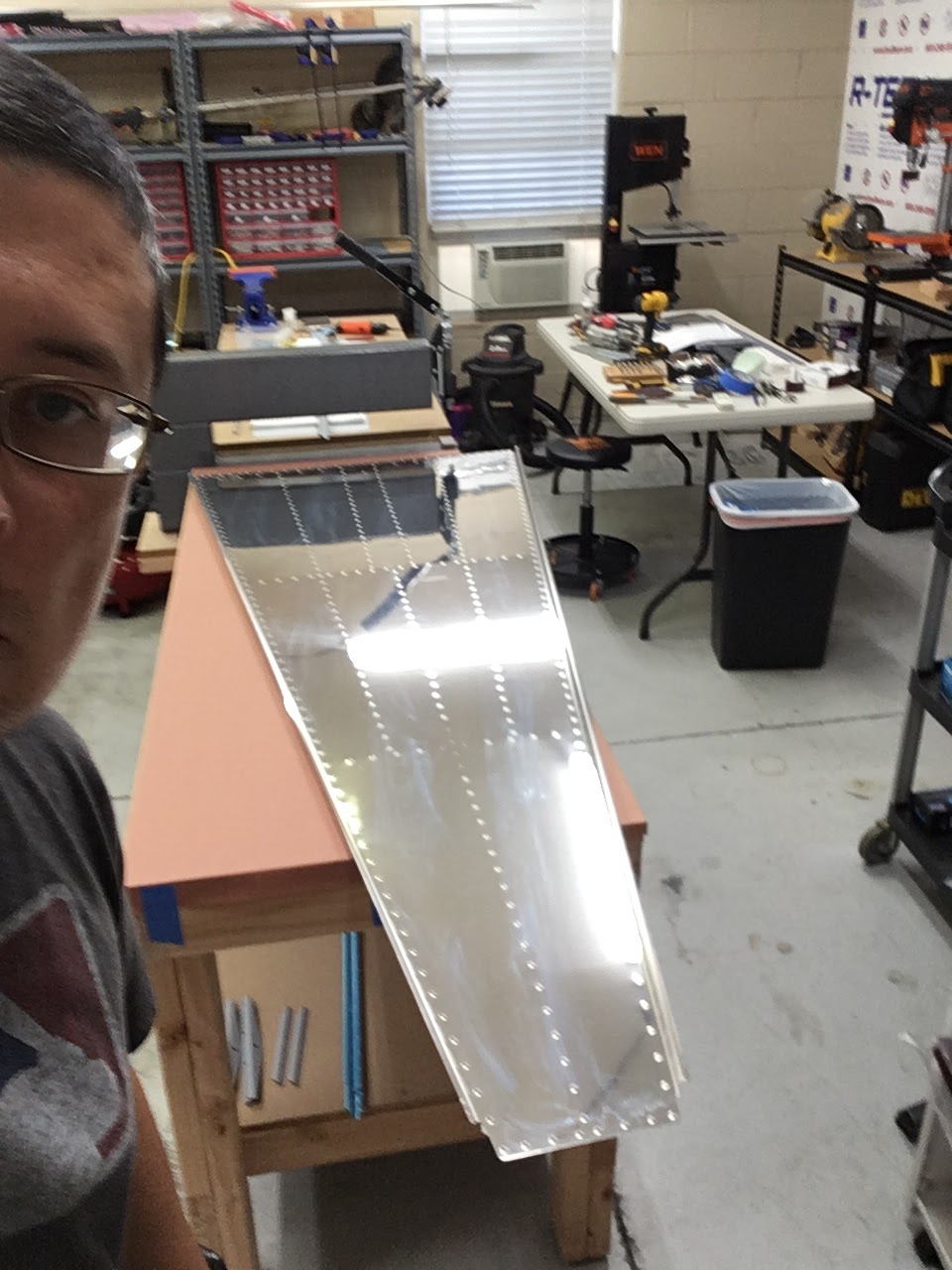
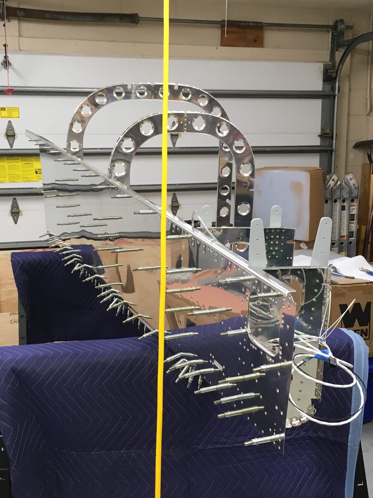
Hung the left side skin and righted the aft fuselage - NOW this kit is finally starting to look like an airplane!

Another view, from the back (yellow wire is just a power cable hanging from ceiling):
A view of the inside:

Aft portion of the wire harness - I loosely coiled the excess for now, to get them off the floor.

Closeup of the aft wire harness - I have not yet fully tightened the cable "zip" ties, thus why the wires are not lying completely straight in the j-channel:

Front portion of the harness - these cable ties are left very loose, since another cable will be added at a later step.

FAA mugshot:

Cool view down the aft fuselage:

Tomorrow (I hope) will involve completing the SB, clecoing the right skin, and then pounding away at a few rivets.
No comments:
Post a Comment