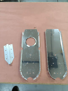
Countersunk rudder stops. The regular countersink cage tool didn't fit due to the flange, so I used a countersink bit-extender (without a cage) and tried to carefully keep an even countersink:
\Primed rudder stops and horizontal stabilizer attach bar:
Oops - those edges are sharp (I hadn't deburred the edges of the bulkheads yet, and sliced my finger on one of them). I'm officially building an airplane now!
I forgot to take a picture when the bulkheads and tie down bracket were attached to the vertical stabilizer for match-drilling, but here is the end result. Who has a 17/64" drill bit required for one of those holes? Turns out, I had one that's about 20 years old.
... and the same for the extra holes in the vert. stabilizer:
Deburred bulkhead edges and holes; dimpled bulkheads; countersunk tie-down bracket; prepped and primed all three parts. Note - there was an error in the plans which called for dimpling of two holes that exist partially behind the tie-down bracket. I guess it is because those are part of the taildragger version of the plans, but were not removed in the tri-gear plans. Of course, I dimpled them, and then when I tried to fit the tie-down bracket, they prevented the bracket from sitting flush. No worries - I just used a double-flat set and squeezed both of them flat again (on both bulkheads). Once primed it is difficult to tell which holes were re-flattened (not that it matters - these parts are not visible on the completed aircraft).


No comments:
Post a Comment