1) riveted nutplates to Gretz mount; started and finished tubing and wiring Garmin GAP-26 heated Pitot/AOA (had to enlarge 8 holes to fit SB500-6 snap bushings)
2) Fabricated left torque tube to bellcrank pushrod; installed left aileron bellcrank upside down)
3) reinstalled left aileron bellcrank correctly; fabricated torque tube subassemblies (CS-00009 and WD-1014)
4) BOTH sides - fabricated flap/aileron cradle; drilled hinge brackets; rod-end rib subassembly (drilled, deburred); hinge pair rib subassembly (drilled, deburred); cut tabs on ribs
5) BOTH sides - deburred all ribs (edges/holes); deburred spars; attached main and nose ribs and hinge assemblies to spars; fabricated trailing edge wedges (VA-140); assembled flap skeletons
6) used new die grinder and cutoff wheel to cut aileron to bellcrank pushrod and torque tube collar; drilled pushrod, match-drilled threaded rod ends, deburred pushrod and rod ends, primed inside of pushrod.
Importantly, Ken B., a fellow RV-14A builder and experienced RV mentor, was kind enough to drive an hour each way to visit my project and check my work ... and (as always) he let me ask him a bunch of questions. Thanks again, Ken!!! It's nice to know that I can "build on" rather than have to redo anything major :)
Finished fabricating the Gretz pitot mount (riveted nutplates, and checked install on wing):
The next series of pics are a bit out of order, but involve wiring and plumbing the Garmin GAP-26 heated pitot/AOA probe. Here is the final heater wiring connection (two male/female fastons) in the access bay of the left wing, partially connected:
Expanded view of tubing and wiring connected to the GAP-26:
3/16" GAP-26 tubing bent to fit down the shaft of the Gretz mount, and capped to convert the end to accept 1/4" nylon tubing:
GAP-26 mounted in Gretz:
AOA (blue) and pitot (red) 1/4" tubing:
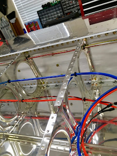
Pitot heat wires (14ga) run through snap bushings. Two notes: 1) I had to enlarge the rib holes to 1/2" for the large SB-500-6 bushings, to accommodate the pitot tubing and the two wires; and, 2) I formed the pitot heat wires into a twisted pair, to cancel electromagnetic forces that might disrupt the magnetometer in flight. In my view, the magnetometer is located far too close to the wiring bundles, but most people who installed only unregulated, heated pitot/AOA reported no issues (the regulated pitot/AOA had issues for some builders, esp. those who either didn't form twisted pairs or run shielded cables):
Pitot/AOA tubing connections:
I may have bought too much extra tubing; but, that's better than too little:
Fabricated the left torque tube to bellcrank pushrod; match-drilling shown here:
Primed parts for the abovementioned tube:
Blind-riveted tube ends:
Attached rod end bearings and jam nuts (loosely ... I'll tighten and torque-stripe them later, Vic S.!)
Installed left aileron bellcrank ... upside down:
Ah, that's better:
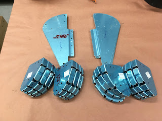
Fabricated two left torque tube subassemblies (CS-00009 and WD-1014):
Fabricated cradles for flaps and ailerons:
Drilled trailing edge of one left flap hinge bracket, followed by match drilling the remaining 3 left brackets:
Deburred brackets and flap nose ribs (both flaps):
Buffed corners of nose ribs (both flaps):
Match and final drilled nose rib doublers (both flaps):
For both flaps: Match-drilled the remaining parts in the picture below, clecoed the ribs to the doublers or hinge brackets as required:
Removed main rib tabs, final drilled, and deburred all ribs for both flaps:
Flap skeleton assemblies:
Fabricated inboard and outboard trailing edges for both flaps (left shown here):
All trailing edges for both flaps shown here:
Purchased a die grinder and cutoff wheel to cut the left bellcrank to aileron pushrod, drilled #40 pilot holes in the pushrod, match drilled #30 holes into threaded rod ends, deburred, and primed pushrod:


No comments:
Post a Comment